
Safety Light Curtain Systems Owner's manual


P/N 68413 rev. A 13
Banner Engineering Corp. • Minneapolis, U.S.A.
www.bannerengineering.com • Tel: 763.544.3164
EZ-SCREEN Point
Instruction Manual
Components and Specifications
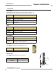
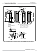
Enclosure Size: See Figure 2-1
Materials: Extruded aluminum housings with yellow polyester powder finish and well-sealed,
rugged molded PBT end caps, acrylic lens cover
Rating: NEMA 4, 13; IEC IP65
Operating conditions Temperature: 0° to +50° C (+32° to 122° F)
Max. Relative Humidity: 95% maximum relative humidity (non-condensing)
Shock and Vibration EZ-SCREEN systems have passed vibration and shock tests according to IEC 61496-1 and -2.
This includes vibration (10 cycles) of 10-55 Hz at 0.35 mm (0.014") single amplitude
(0.70 mm peak-to-peak) and shock of 10 g for 16 milliseconds (6,000 cycles).
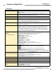
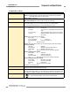
Status Indicators 7-Segment Diagnostic Indicators, Both Emitter and Receiver
Dash (–) or L = System is OK
Error Codes = See Section 5.1 for code definitions and recommended
action
Scan code setting = Appears during power-up or after scan code is changed.
(C1 or C2) (Temporary indication; normal display resumes within a
few seconds.)
Emitter: One bi-color (red/green) Status indicator
Green steady = RUN mode
Green single flashing = TEST mode
Red single flashing = Lockout (see Section 5.1.2)
OFF = No power to sensor
Receiver: Two system Status indicators, plus one bi-color (red/green) Beam Status indicator
Yellow Reset Indicator
ON steady = RUN mode
Double flashing = Waiting for manual reset after power-up
Single flashing = Waiting for manual latch reset
OFF = No power to sensor or system is not ready for operation
Bi-Color (Red/Green) Status Indicator
Green steady = Outputs ON
Red steady = RUN mode, outputs OFF
Red single flashing = Lockout (see Section 5.1.1)
OFF = No power to sensor or system is not ready for operation
Bi-Color (Red/Green) Beam Status Indicator
Green steady = Clear beam, strong signal
Green flickering = Clear beam, weak signal
Red steady = Beam blocked
OFF = No power to sensor or no scanning
See Figure 1-5 for indicator locations.
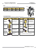
Mounting Hardware Emitter and receiver each are supplied with a pair of swivel end mounting brackets. Mounting
brackets are 8-gauge cold-rolled steel, black zinc finish.
Cables and Connections Cables are user-supplied. Wiring terminals accommodate one 22 to 16 ga. wire or two wires up
to 18 ga.; Pg13.5 wiring chamber access port capacity varies, depending on cable gland or strain
relief fitting used. Supplied cable gland is for a cable diameter of 6 to 12 mm (0.236" to 0.472").
Certifications
US
Other certifications pending; contact factory for further information
2.6 Specifications, continued