
Safety Light Curtain Systems Owner's manual


12 P/N 68413 rev. A
Banner Engineering Corp. • Minneapolis, U.S.A.
www.bannerengineering.com • Tel: 763.544.3164
EZ-SCREEN Point
Instruction Manual
Components and Specifications
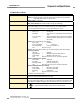
2.6 Specifications
Supply Voltage (V in) 24V dc ±15%, 10% maximum ripple
Emitter: 100 mA max.
Receiver: 500 mA max., exclusive of OSSD1 and OSSD2 loads (up to an additional 0.5A each)
Short Circuit Protection All inputs and outputs are protected from short circuits to +24V dc or dc common
(except Emitter AUX power connections; see Section 3.5)
Response Time 24 milliseconds or less from interruption of light beam to safety outputs going to OFF-state
Safety Rating Type 4 per IEC 61496-1, -2; Category 4 per ISO 13849-1/EN 954-1
EDM Input +24V dc signals from external device contacts can be monitored (single-channel, dual-channel
or no monitoring) via EDM1 and EDM2 terminals in the receiver (see Section 3.7.3). Monitored
devices must respond within 200 milliseconds of an output change.
Reset Input The Reset input must be high (10 to 30V dc at 30 mA) for 0.25 to 2 seconds and then low (less
than 3V dc) to reset the receiver.
Remote Test Input Test mode is activated either by applying a low signal (less than 3V dc) to emitter TEST1
terminal for a minimum of 50 milliseconds, or by opening a switch connected between TEST1
and TEST2 terminals for a minimum of 50 milliseconds. Beam scanning stops to simulate a
blocked condition. A high signal (10 to 30V dc, 35 mA inrush, 10 mA max.) at TEST1 terminal de-
activates Test mode and allows the emitter to operate normally. TEST1 and TEST2 are factory
jumpered. (See Section 3.7.4 for more information.)
Output Signal Switching Devices
(OSSDs)
(See Warnings on page 35)
Two redundant solid-state 24V dc, 0.5 A max. sourcing OSSD (Output Signal Switching Device)
safety outputs. (Use optional interface modules for ac or larger dc loads.)
Capable of the Banner “Safety Handshake” (see Section 1.1).
ON-State voltage: ≥Vin-1.5V dc
OFF-State voltage: 1.2V dc max. (0-1.2V dc)
Max. load capacitance: 0.1 µF
Max. load inductance: 10 H
Leakage Current: 0.50 mA maximum
Cable Resistance: 10 Ω maximum
OSSD test pulse width: 100 to 300 microseconds
OSSD test pulse period: 5 ms to 27 ms (varies with number of beams)
Switching Current: 0 - 0.5 A
Controls and Adjustments
Emitter:
Scan code selection: 2-position switch (code 1 or 2). Factory default position is 1.
Receiver:
Scan code selection: 2-position switch (code 1 or 2). Factory default position is 1.
Trip/latch output selection: redundant switches. Factory default position is L (latch).
EDM/MPCE monitor selection: redundant switches select between 1- or 2-channel monitoring.
Factory default position is 2.
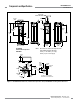
Emitter/Receiver Operating Range
(See Cautions on pages 6 and 10)
Short-range models: 0.8 m to 20 m (2.6' to 65') See Warnings on pages 6 and 7.
Long-range models: 15 m to 70 m (49' to 230')
Range decreases with use of mirrors and/or lens shields; see Section 2.2.
ACCESS-GUARD Kit: 0.4 m to 8 m (2.6' to 26')
Beam Diameter 25 mm (1")
Ambient Light Immunity > 10,000 lux at 5° angle of incidence
Strobe Light Immunity Totally immune to one Federal Signal Corp. “Fireball” model FB2PST strobe
Emitter Element Infrared LED, 880 nm at peak emission
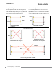
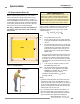
Effective Aperture Angle
(EAA)
Meets Type 4 requirements per IEC 61496-2, Section 5.2.9
Short-range models: ± 2.5° @ 3 m
Long-range models: ± 2.5° @ 15 m