EZ-SCREEN™ Point Instruction Manual Features • N on-contact safety device for perimeter and access guarding from dangerous machinery • D iverse-redundant and self-checking design to achieve control reliability and meet IEC 61496-1 type 4 requirements • S elf-contained two-part system is optically synchronized: ‑‑‑ Needs no external controller Needs no extra synchronization wire Easy and economical to install • O perating range 0.8 to 20 m or 15 to 70 m (2.
Table of Contents Important ... read this before proceeding! In the United States, the functions that the Banner MMDTA-11B and MMD-TA-12B Muting Modules are intended to perform are regulated by the Occupational Safety and Health Administration (OSHA). Outside of the United States, these functions are regulated by a variety of agencies, organizations, and governments.
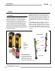
EZ-SCREEN Point Overview Instruction Manual 1. Overview 1.1 Introduction The Banner EZ-SCREEN™ Point System creates an optically synchronized, microprocessor-controlled, opposed-mode optoelectronic light beam. This economical two-part system consists of an emitter and receiver. The system requires no external controller or sync wire between the emitter and receiver; the microprocessors are located within the receiver.
Overview When multiple systems are used together in a grid, the beam configuration (number of beams and beam spacing) required for an application is determined by the application and the safety standards being followed. U.S. applications are based on recommendations in ANSI/RIA R15.06 and ANSI B11. European applications are based on recommendations in EN 999. See pages 63 and 64 for a list of applicable safety standards.
EZ-SCREEN Point Overview Instruction Manual 1.2 Applications and Limitations WARNING . . . Not for Point-of- The Banner EZ-SCREEN Point System is designed for use in access-guarding and perimeter-guarding applications. It is designed to be installed in multiple sensor pairs, with the beams stacked vertically, in order to detect a body or torso (rather than a hand or an arm) as a person enters a hazardous area.
EZ-SCREEN Point Overview Pass-through hazards: Perimeter- and access-guarding applications must be designed to prevent pass-through hazards. A pass-through hazard occurs when an individual is allowed to cross the safeguard (which issues a stop command to remove the hazard). Subsequently, the person may cross into the hazardous area but their presence is no longer detected. A danger arises because the machine’s dangerous motion may resume while personnel are within the safeguarded area.
EZ-SCREEN Point Overview Instruction Manual 1.4 EZ-SCREEN Point Operating Features 1.3 Control Reliability In addition to physical location requirements, safety standards require a safety system such as the EZ-SCREEN Point to fulfill some internal requirements. For example, for an optical safety system to be used in a Safety Category 4 application (per EN954-1), it must be third-party certified to the type 4 requirements of IEC 61496-1 and -2.
EZ-SCREEN Point Overview If trip output is selected, the OSSD outputs will turn ON after power is applied, and the receiver passes its internal self-test/ synchronization and recognizes that the beam is clear. The trip output will also automatically reset after all beam interruptions are cleared. If latch output is selected, the EZ-SCREEN requires a manual reset for the OSSD outputs to turn ON, after power is applied and the beam is clear (see Section 4.2.1).
EZ-SCREEN Point Components and Specifications Instruction Manual 2. System Components and Specifications 2.1 Models Available Banner EZ-SCREEN Point components may be purchased individually or in kits. Kits (as indicated below) include one emitter, one receiver, a keyed reset switch, two cable glands, two spanner wrenches, a test piece, and standard mounting hardware for both sensors.
EZ-SCREEN Point Components and Specifications Instruction Manual 2.
EZ-SCREEN Point Components and Specifications Instruction Manual 2.3 Accessories Interface Modules Interface modules provide isolated safety contacts for a Primary Safety Device (the EZ-SCREEN Point System). See data sheet p/n 62822 for more information. Model Description LAT-1 Laser Alignment Tool with adapter clip EZA-LAT-1 Clip-on retroreflective target BRT-THG-2-100 50 mm (2") wide reflective tape, 2.5 m (100") long BT-1 Beam Tracker Cabling Models Description SI-QS-CG13 Pg13.
EZ-SCREEN Point Components and Specifications Instruction Manual Mirrors NOTE: The total range decreases by approximately 8% per mirror. Models SSM-100 Reflective Area Y 100 mm (3.9") M6 x 19 mm screw (4 supplied) Mounting L1 Height L2 Height L3 211 mm (8.3") 178 mm (7.0") 153 mm (6.0") 101.2 mm (3.98") M5 x 10 mm screw (4 supplied) Y L3 L1 L2 100 mm (3.94") 115 mm (4.53") Accessory Mounting Brackets NOTE: EZA-MBK-1 Standard end cap bracket kit is included with emitter and receiver.
EZ-SCREEN Point Components and Specifications Instruction Manual 2.4 Replacement Parts Model 2.5 Literature Description MGA-KS0-1 Keyed reset switch (same as that included in kits) MGA-K-1 Replacement key for switch MGA-KS0-1 EZA-AP-1 Access port plug with o-ring EZA-CP-13 Pg13.
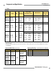
EZ-SCREEN Point Components and Specifications Instruction Manual 2.6 Specifications Supply Voltage (V in) 24V dc ±15%, 10% maximum ripple Emitter: 100 mA max. Receiver: 500 mA max., exclusive of OSSD1 and OSSD2 loads (up to an additional 0.5A each) Short Circuit Protection All inputs and outputs are protected from short circuits to +24V dc or dc common (except Emitter AUX power connections; see Section 3.
EZ-SCREEN Point Components and Specifications Instruction Manual 2.6 Specifications, continued Enclosure Size: See Figure 2-1 Materials: Extruded aluminum housings with yellow polyester powder finish and well-sealed, rugged molded PBT end caps, acrylic lens cover Rating: NEMA 4, 13; IEC IP65 Operating conditions Temperature: 0° to +50° C (+32° to 122° F) Max.
EZ-SCREEN Point Components and Specifications Instruction Manual 12.5 mm (0.50") Minimum Bend Radius 16.7 mm (0.66") See Notes Below EZ-SCREEN Point EZ-SCREEN Point BANNER ENGINEERING CORP., USA 888.373.6767 BANNER ENGINEERING CORP., USA 888.373.6767 26 mm (1.02") 107.0 mm (4.21") 52 mm (2.0") 1 BEAM 55 mm (2.1") 1 BEAM R E S E T S T A T U S 149 mm (5.9") S T A T U S R E S E T 124 mm (4.9") 25 mm (1.0") 182 mm (7.2") 60.0 mm (2.36") EZ-SCREEN Standard Mounting Bracket EZA-MBK-1 74.
EZ-SCREEN Point Instruction Manual System Installation 3. Installation and Alignment Read Section 3 in its entirety before installing the Banner EZ-SCREEN Point System. The EZ-SCREEN System’s ability to perform its safety guarding function depends upon the appropriateness of the application and upon its proper mechanical and electrical installation and interfacing to the guarded machine.
EZ-SCREEN Point System Installation 3.2 Security Protocol Certain procedures for installing, maintaining and operating the EZ-SCREEN Point system must be performed by either Designated Persons or Qualified Persons. A Designated Person is identified and designated in writing, by the employer, as being appropriately trained and qualified to perform the specified checkout procedures on the EZSCREEN system. A machine operator so designated may be a Designated Person.
EZ-SCREEN Point System Installation Instruction Manual Sensing Mode Configurations In opposed-mode configuration, the emitter and receiver are mounted opposite from each other to form a single beam (see Figure 3-3). Opposed-mode configuration can be combined with vertical corner mirrors for perimeter-guarding applications, as shown in Figure 3-4 and described in Section 3.3.6.
EZ-SCREEN Point System Installation Instruction Manual 3.3.2 Minimum Separation Distance (Ds) Notice Regarding MPCEs Minimum Separation (Safety) Distance (Ds) is the minimum distance required between the light beam(s) and the closest reachable hazard point.
EZ-SCREEN Point System Installation Instruction Manual CAUTION . . . Position Components Carefully The emitter(s) and receiver(s) must be positioned so that the hazard cannot be accessed by reaching over, under, around or through the sensing field. Supplemental safeguarding may be required; see Section 3.3.3. CAUTION . . . Adequate Separation Distance The emitter(s) and receiver(s) must be positioned a safe distance from hazardous areas, as described by OSHA standards in Section 1910.
EZ-SCREEN Point System Installation Supplemental safeguarding is used to make the hazard point accessible only through the light grid, per ANSI/RIA R15.06. This means that mechanical barriers (such as screens or bars) or supplemental safeguarding must be installed, wherever needed, to prevent any person from entering into or remaining in the hazard area undetected. The use of mechanical barriers for this purpose is called hard guarding (see the Warning at left and Figure 3-7).
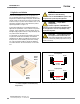
EZ-SCREEN Point System Installation Instruction Manual 3.3.4 Emitter/Receiver Orientation E The emitter and receiver must be mounted vertically, and parallel to each other. Otherwise dangerous voids in the light grid could allow objects or personnel to pass undetected through the grid (see Figure 3-8). Be certain the light grid covers R all access to the guarded area not otherwise protected by hard guarding or other supplemental guarding.
EZ-SCREEN Point System Installation Instruction Manual 3.3.5 Adjacent Reflective Surfaces WARNING . . . Avoid Installation Near A reflective surface located adjacent to the light beam(s) may deflect light around an object in the beam(s). In the worst case, such a situation may allow an object to pass undetected through the beam(s). This reflective surface may result from shiny surfaces or glossy paint on the machine, the workpiece, the floor or the walls.
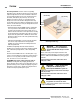
EZ-SCREEN Point System Installation Instruction Manual 3.3.6 Use of Corner Mirrors EZ-SCREEN Systems may be used with one or more vertical corner mirrors in perimeter-guarding applications (see Section 2.2 for availability). The use of corner mirrors reduces the maximum specified emitter/receiver separation by approximately 8 percent per mirror (see Section 3.4). Mirrors are not allowed for applications that would allow personnel undetected access into the safeguarded area. WARNING . . .
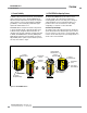
EZ-SCREEN Point System Installation Instruction Manual Emitter EZ-GU ARD BANNER ENGINEERI 888.373.676 NG Grid CORP., 7 USA E D T M 1 2 SCAN CODE ON 1 1 E D T M 1 1 L 2 2 3 L 4 2 1 2 BEAMS Scan Code 2 R E S E T S T A T U S Orient two systems so that their receivers face in different directions. (This applies Emitter Receiver not only to multiple EZ-SCREEN Systems, Receiver but also to EZ-SCREEN Systems Scan Receiver used with other photoelectric Code 2 Scan systems.) Receiver 3.3.
EZ-SCREEN Point System Installation Instruction Manual 3.4 Mechanical Mounting Procedure Short-range emitters and receivers may be mounted up to 20 m (65') apart. Long-range emitters and receivers may be mounted between 15 m (49') and 70 m (230') apart. If Banner SSM corner mirrors are used, the total range decreases by approximately 8 percent per mirror, as follows: The emitter and the receiver must be mounted parallel to each Corner Mirrors* Short-Range Systems Long-Range Systems 1 18.
EZ-SCREEN Point System Installation Instruction Manual Mounting the Sensors Installation Without Mirrors If the floor has a dip, as for a drain, or is raised up within the path of the beams, corrective measures must be taken to ensure that the requirements of ANSI/RIA R15.06, ANSI B11 or EN999 are met (see Figure 3-13). It is important that the distances between the top and bottom beams and the floor meet the requirements of the applicable standards, throughout the length of the beam path.
EZ-SCREEN Point System Installation Instruction Manual Installations With Corner Mirrors If corner mirrors are used in the application, measure and position them as for the sensors. Refer to the data sheet packed with the mirrors for specific installation instructions. 1. Follow emitter/receiver installation steps 1-3 for installation without mirrors. 2. Mount the mirror(s) at the desired locations, parallel to the emitter and receiver. (Use a level to verify plumb, if the floor surface is level.
EZ-SCREEN Point System Installation Instruction Manual For easy wiring, each EZ-SCREEN sensor has a removable modular terminal block inside one end cap, at the same end as the indicators (See Figure 3-14). To make connections: 1. Remove the wiring chamber end cap by unscrewing the four captive screws in the end cap corners. 2. Remove the terminal block from the end cap. 3. Remove one or more of the three Pg13.5 plugs, as needed, from their threaded access ports, using the accessory spanner wrench.
EZ-SCREEN Point System Installation Instruction Manual Reset Switch Hookup Connect the external Reset switch to the Reset terminal on the receiver terminal block and to 24V dc (see Figures 3-19, 3-20 and 3-21). Configuring the System for Initial Checkout Verify that the System is set to the factory presets for initial checkout and optical alignment. (Factory presets are for Latch Output, 2-Channel EDM, and Scan Code 1; receiver terminals 6 and 7 should be connected, as described in step 4 above.
EZ-SCREEN Point System Installation Instruction Manual Optical Alignment Procedure After the emitter and receiver are mechanically aligned (perpendicular to the floor along the path of the beams, and plumb in all possible directions), optically align them, first using the LAT-1, if desired, and finally using the receiver Beam Status indicator. Using the LAT-1 for Alignment The LAT-1 Laser Alignment Tool (see Section 2.
EZ-SCREEN Point System Installation Instruction Manual 1. A ttach the battery-powered LAT-1 to the housing of the emitter over the beam location, using the EZ-SCREEN bracket clip included with the tool. A dot on the sensor housing next to the lens window indicates the beam’s location. Align the hole on the LAT-1 over the beam marking (see Figure 3-15).
EZ-SCREEN Point System Installation 3.7 Electrical Interface to the Guarded Machine (Permanent Hookup) Make the electrical connections as described in Sections 3.7.1 to 3.7.4 as required by each individual application. Supply power and the external Reset switch should be previously connected by this point. The EZ-SCREEN must also have been aligned and passed the Initial Checkout, as described in Section 3.6.
EZ-SCREEN Point Instruction Manual 2-Channel (Dual-Channel) Control Two-channel control provides the ability to electrically extend the safe switching point beyond the FSD contacts. With proper monitoring (i.e. EDM), this method of interfacing is capable of detecting certain failures in the control wiring between the safety stop circuit and the MPCEs.
EZ-SCREEN Point System Installation 3.7.3 Machine Primary Control Elements and EDM Inputs Each of the two Machine Primary Control Elements (MPCE1 and MPCE2) must be capable of immediately stopping the dangerous machine motion, irrespective of the state of the other. These two channels of machine control need not be identical, but the stop time performance of the machine (Ts, used to calculate the separation distance, see Section 3.3.1) must take into account the slower of the two channels.
EZ-SCREEN Point System Installation Instruction Manual WARNING . . . Proper Wiring +24V dc 0V dc The generalized wiring configurations shown are provided only to illustrate the importance of proper installation. EZ-SCREEN Emitter PE 1 dc Com 2 The proper wiring of the EZ-SCREEN System to any particular machine is solely the responsibility of the installer and end user. +24V dc 3 TEST2 4 TEST1 5 Open to test (1) or 1) TEST input must be jumpered if not used.
EZ-SCREEN Point System Installation Instruction Manual +24V dc 0V dc WARNING . . . Proper Wiring The generalized wiring configurations shown are provided only to illustrate the importance of proper installation. EZ-SCREEN Receiver PE 1 dc Com 2 +24V dc 3 (Not Used) 4 (1) RESET 5 EDM1 6 EDM2 7 + + Reset (2) CAUTION. . . Shock Hazard OSSD1 8 OSSD2 9 Always disconnect all power from the EZ-SCREEN System and the guarded machine before making any connections or replacing any component.
EZ-SCREEN Point System Installation Instruction Manual WARNING . . . +24V dc 0V dc Proper Wiring The generalized wiring configurations shown are provided only to illustrate the importance of proper installation. EZ-SCREEN Receiver PE 1 dc Com 2 The proper wiring of the EZ-SCREEN System to any particular machine is solely the responsibility of the installer and end user. +24V dc 3 (Not Used) 4 (1) RESET 5 EDM1 6 CAUTION. . .
EZ-SCREEN Point Operating Instructions Instruction Manual 4. System Operation Trip or Latch Output mode is selected on two DIP switches in the receiver configuration port; see Figure 4.1. Both switches must be set to the same setting. If they have different settings, an error code will be displayed. 4.
EZ-SCREEN Point Operating Instructions Instruction Manual 4.2 Reset Procedures 4.2.1 Receiver Resets The EZ-SCREEN Point receiver has a RESET input, terminal 5, that allows the System to be manually reset. To reset the receiver, close the Reset switch for 1/4 to 2 seconds, then open the Reset switch. (If Reset switch model MGA-KS0-1, listed in Section 2, is used, close the switch by turning the key 1/4 turn clockwise; open it by turning the key counterclockwise, back to its original position.
EZ-SCREEN Point Operating Instructions Instruction Manual Receiver: A bi-color red/green Beam Status indicator shows whether the beam is aligned and clear with a strong signal, clear but with a weak signal, or is blocked and/or misaligned. A yellow Reset indicator shows when the System is in Run mode or is waiting for a reset. A bi-color red/green Status indicator shows when the OSSD outputs are ON (green) or OFF (red), or the System is in lockout mode (flashing red).
EZ-SCREEN Point Instruction Manual 4.4 Normal Operation System Power-Up The System will power up in one of two ways, depending on the Trip/Latch output configuration. If the System is set for Trip output, it will power up and reset automatically; if the System is set for Latch output, it will require a manual reset procedure after power-up and sensor alignment.
Troubleshooting and Maintenance EZ-SCREEN Point Instruction Manual 5. Troubleshooting and Maintenance Evaluate status indicators per Section 4.3. 5.1 Troubleshooting Lockout Conditions A lockout condition causes all of the EZ-SCREEN OSSD outputs to turn or remain OFF, sending a “stop” signal to the guarded machine. Each sensor provides diagnostic error codes to assist in the identification of the cause(s) of Lockouts (see Figure 5-1). The System provides easy methods for determining operating problems.
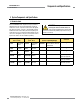
EZ-SCREEN Point Troubleshooting and Maintenance Instruction Manual 5.1.1 Receiver Error Codes Refer to Figure 5-1 for a full description of receiver error codes and what to do when they occur. Diagnostic Display Error Description Appropriate Action Output Error – caused by • one or both outputs being shorted to a power supply (high or low), • by shorting OSSD 1 to OSSD 2, or • by an overload (greater than 0.5A). • Disconnect the OSSD loads and reset the receiver.
EZ-SCREEN Point Troubleshooting and Maintenance Diagnostic Display Error Description Instruction Manual Appropriate Action DIP Switch Error This error can be caused by incorrect DIP switch settings or by changes to the DIP switch settings when the system is on. • Verify that the DIP switch settings are valid (per Section 4.1). Make any corrections necessary and perform a receiver reset.
EZ-SCREEN Point Troubleshooting and Maintenance Instruction Manual 5.1.2 Emitter Error Codes NOTE: The emitter flashes the number 2 followed by the other error code digit, pauses, then flashes the sequence again. Diagnostic Display Error Description Appropriate Action Test Input Error This error can occur if excessive noise is present on the test input. • Reset the emitter by disconnecting and reapplying power to the emitter (see Section 4.2).
EZ-SCREEN Point Troubleshooting and Maintenance 5.2 Electrical and Optical Noise The EZ-SCREEN System is designed and manufactured to be highly resistant to electrical and optical noise and to operate reliably in industrial settings. However, serious electrical and/or optical noise may cause a random trip or latch condition. In very extreme electrical noise cases, a lockout is possible.
EZ-SCREEN Point Instruction Manual 5.3 Test Mode Opening a switch or relay contacts connected to the TEST1 and TEST2 terminals of the emitter, or supplying a voltage of less than 3V dc to TEST1 only, simulates a blocked condition, for testing purposes. To verify proper operation, measure the voltage between TEST1 (terminal 5) and dc COM (terminal 2 or 8) of the emitter: • If the voltage is 10 to 30V dc, the emitter should be in Run mode and beam scanning should be occurring.
EZ-SCREEN Point Periodic Checkout Procedures Instruction Manual 6. Periodic Checkout Procedures Study each procedure from beginning to end before you start to make sure that you understand each step. Refer all questions to the Banner Applications Engineering Department at the address or numbers listed on the front cover of this manual. Checkouts must be performed as detailed in Section 6.1 below and results should be recorded and kept in the appropriate place (e.g.
EZ-SCREEN Point Periodic Checkout Procedures Instruction Manual I f mirrors are used in the application: Test the beam at three points on each leg of the beam path (emitter to mirror, and between mirror and receiver). See Figure 6-2. Emitter Receiver dir AS U R D 888.373 E M D M T 1 1 T 2 G DR AU G 2 3 NO 2 L 2 1 L 1 1 4 3 ON 2 1 1 ,.P RO CG N 76 IRE 76 EN .3 I E 73.8 GNE 8 RE D E 8 NN M D AB 1 T M 1 T 2 4 -ZE GridUSA D UAR CORP., ERING .
Periodic Checkout Procedures 6.3 Commissioning Checkout Perform this checkout procedure as part of System installation (after the System has been interfaced to the guarded machine as described in Section 3.7), or whenever changes are made to the System (either a new configuration of the EZ-SCREEN System or changes to the machine). A Qualified Person (as defined in the Safety Glossary) must perform the procedure; checkout results should be recorded and kept on or near the guarded machine, per OSHA 1910.
EZ-SCREEN Point Instruction Manual 13. R emove electrical power to the EZ-SCREEN System. All OSSD outputs should immediately turn OFF, and should not be capable of turning ON until power is re-applied and, if in Latch Output mode, a manual reset is performed (Trip Output mode requires no manual reset). 14.
Periodic Checkout Procedures EZ-SCREEN Point Instruction Manual 6.5 Semi-Annual Checkout Perform this checkout procedure every six months following System installation. A Qualified Person (as defined in the Safety Glossary) must perform the procedure; checkout results should be recorded and kept on or near the guarded machine, per OSHA 1910.217(e)(1). 1. Perform the commissioning checkout procedure (Section 6.3).
EZ-SCREEN Point Glossary of Terms Instruction Manual Glossary of Safety Terms Terms shown in italics in the definitions below are themselves defined elsewhere in the glossary. ANSI (American National Standards Institute): An association of industry representatives which develops technical standards, including safety standards. These standards represent a consen sus from a variety of industries on good practice and design.
Glossary of Terms Machine secondary control element (MSCE): A machine control element independent of the Machine Primary Control Element(s) (MPCEs), capable of removing the source of power from the prime mover of the relevant dangerous machine parts. MPCE monitor contacts: The normally closed contacts of a guarded machine’s MPCEs which are connected to the EZ-SCREEN System EDM inputs. These contacts must be mechanically linked to the control elements (forced-guided).
EZ-SCREEN Point Instruction Manual Notes Banner Engineering Corp. • Minneapolis, U.S.A. www.bannerengineering.com • Tel: 763.544.3164 P/N 68413 rev.
Notes EZ-SCREEN Point Instruction Manual Banner Engineering Corp. • Minneapolis, U.S.A. 56 P/N 68413 rev. A www.bannerengineering.com • Tel: 763.544.
SOURCES OSHA Documents Superintendent of Documents Government Printing Office P.O. Box 371954 Pittsburgh, PA 15250-7954 Tel: (202) 512-1800 http://www.osha.gov ANSI Accredited Standards American National Standards Institute (ANSI) 11 West 42nd Street New York, NY 10036 Tel: (212) 642-4900 http://www.ansi.org B11 Documents Safety Director The Association for Manufacturing Technology (AMT) 7901 Westpark Drive McLean, VA 22102 Tel: (703) 893-2900 http://www.mfgtech.org U.S. Application Standards ANSI B11.
WARRANTY: Banner Engineering Corp. warrants its products to be free from defects for one year. Banner Engineering Corp. will repair or replace, free of charge, any product of its manufacture found to be defective at the time it is returned to the factory during the warranty period. This warranty does not cover damage or liability for the improper application of Banner products. This warranty is in lieu of any other warranty either expressed or implied. P/N 68413 rev. A Banner Engineering Corp.