
Safety Light Curtain Systems Owner manual


page 25
Banner Engineering Corp. • Minneapolis, MN U.S.A.
www.bannerengineering.com • Tel: 763.544.3164
EZ-SCREEN Grid
Instruction Manual
Installation and Alignment
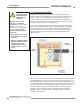
3.3.6 Avoiding Electrical and Optical Noise
The EZ-SCREEN System is designed and manufactured to
be highly resistant to electrical and optical noise and to
operate reliably in industrial settings. However, extreme
electrical and/or optical noise may cause a random trip or
latch condition. In very extreme cases, a lockout is
possible. Care should be taken to avoid sources of
interference when planning the mounting location.
When planning the installation, the following
should be considered:
• Provide a good connection between each
sensor and earth ground;
•Avoid routing sensor input or output wires
close to “noisy” wiring; and
•Avoid optical interference from adjacent light
grids or other photoelectrics.
See Section 5.2 for additional information.
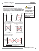
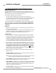
3.3.7 Multiple-System Applications
Whenever EZ-SCREEN Grid Systems operate in
close proximity with other photoelectric devices
(EZ-SCREEN Grid Systems, safety light screens,
or other photoelectric sensors), optical crosstalk
may potentially take place between systems.
Because EZ-SCREEN sensors operate at long
ranges, it is especially important to carefully
consider the placement of multiple sensor pairs
prior to installation.
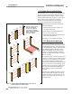
To minimize crosstalk, alternate the emitters and
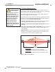
receivers, as shown in Figure 3-8. When three or
more systems are installed more or less parallel
to one another, optical crosstalk may occur
between sensor pairs whose emitter and receiver
lenses are oriented in the same direction. In this
situation, mount the sensor pairs exactly in line
with each other, and/or add an opaque light
barrier between the pairs to control optical
crosstalk.
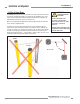
To further aid in avoiding crosstalk, the sensors
feature a two-position selectable scan code. A
receiver set to one scan code will not “see” an
emitter set to another code. See Section 4.1 for
more information.
1
1
O
N
2
34
S
C
A
N
C
O
D
E
2
1
T
L
1
2
T
L
1
E
D
M
E
D
M
2
S
T
A
T
U
S
B
E
A
M
S
1
2
R
E
S
E
T
S
T
A
T
U
S
E
Z
-
G
U
A
R
D
G
r
i
d
B
A
N
N
E
R
EN
G
I
NE
E
R
IN
G
C
O
R
P
.
,
U
S
A
8
8
8
.
3
7
3
.
6
7
6
7
1
1
O
N
2
3
4
S
C
A
N
C
O
D
E
2
1
T
L
1
2
T
L
1
E
D
M
E
D
M
2
S
T
A
T
U
S
B
E
A
M
S
1
2
R
E
S
E
T
S
T
A
T
U
S
E
Z
-
G
U
A
R
D
G
r
i
d
B
A
N
N
E
R
EN
G
IN
E
E
R
IN
G
CO
R
P
.
,
U
S
A
8
8
8
.
3
7
3
.
6
7
6
7
Emitter
Emitter
Receiver
Scan
Code 1
Scan
Code 2
Receiver
1
1
O
N
2
3
4
S
C
A
N
C
O
D
E
2
1
T
L
1
2
T
L
1
E
D
M
E
D
M
2
S
T
A
T
U
S
B
E
A
M
S
1
2
R
E
S
E
T
S
T
A
T
U
S
E
Z
-
G
U
A
R
D
G
r
i
d
B
AN
N
E
R
EN
G
I
N
E
E
R
IN
G
CO
R
P
.
,
U
S
A
8
8
8
.
3
7
3
.
6
7
6
7
1
1
O
N
2
3
4
S
C
A
N
C
O
D
E
2
1
T
L
1
2
T
L
1
E
D
M
E
D
M
2
S
T
A
T
U
S
1
2
S
T
A
T
U
S
EZ
-
G
U
A
R
D
G
r
i
d
B
A
N
N
E
R
E
N
G
I
N
E
E
R
I
N
G
C
OR
P
.
,
U
S
A
8
8
8
.
37
3
.
6
7
6
7
Emitter
Horizontal
Light Screen
Emitter
Receiver
Horizontal
Light Screen
Receiver
Scan
Code 1 or 2
1
1
O
N
2
34
S
C
A
N
C
O
D
E
2
1
T
L
1
2
T
L
1
E
D
M
E
D
M
2
S
T
A
T
U
S
B
E
A
M
S
1
2
R
E
S
E
T
S
T
A
T
U
S
E
Z
-
G
U
A
R
D
G
r
i
d
B
A
N
N
ER
E
N
G
I
NE
E
R
I
N
G
C
O
R
P
.
,
U
S
A
8
8
8
.
3
7
3
.
6
7
6
7
Emitter
Receiver
1
1
O
N
2
3
4
S
C
A
N
C
O
D
E
2
1
T
L
1
2
T
L
1
E
D
M
E
D
M
2
S
T
A
T
U
S
B
E
A
M
S
1
2
R
E
S
E
T
S
T
A
T
U
S
EZ
-
G
U
A
R
D
G
r
i
d
B
A
N
N
ER
EN
G
I
N
E
E
R
I
N
G
C
O
R
P
.
,
U
S
A
8
8
8
.
3
73
.
6
7
6
7
Emitter
Receiver
Scan
Code 1
Scan
Code 2
1
1
O
N
2
3
4
S
C
A
N
C
O
D
E
2
1
T
L
1
2
T
L
1
E
D
M
E
D
M
2
S
T
A
T
U
S
B
E
A
M
S
1
2
R
E
S
E
T
S
T
A
T
U
S
E
Z
-
G
U
A
R
D
G
r
i
d
B
A
N
N
E
R
E
N
G
I
N
E
E
R
I
N
G
C
O
R
P
.
,
U
S
A
8
8
8
.
3
7
3
.
6
7
6
7
1
1
O
N
2
3
4
S
C
A
N
C
O
D
E
2
1
T
L
1
2
T
L
1
E
D
M
E
D
M
2
S
T
A
T
U
S
B
E
A
MS
1
2
R
E
S
E
T
S
T
A
T
U
S
E
Z
-
G
U
A
R
D
G
r
i
d
B
A
N
N
E
R
E
N
G
I
N
E
E
R
I
N
G
C
O
R
P
.
,
U
S
A
8
8
8
.
3
7
3
.
6
7
6
7
Emitter
#1
Emitter
#2
Opaque Shield
Receiver
#1
Emitter
#3
Receiver
#3
Receiver
#2
1
1
O
N
2
3
4
S
C
A
N
C
O
D
E
2
1
T
L
1
2
T
L
1
E
D
M
E
D
M
2
S
T
A
T
U
S
B
E
A
M
S
1
2
R
E
S
E
T
S
T
A
T
U
S
E
Z
-
G
U
A
R
D
G
r
i
d
B
A
N
N
E
R
E
N
G
I
N
E
E
R
I
N
G
C
O
R
P
.
,
U
S
A
8
8
8
.
3
7
3
.
6
7
6
7
Scan
Code 1
Scan
Code 2
Scan
Code 2
Figure 3-8. Mounting multiple EZ-SCREEN emitters and receivers to
mechanically prevent optical crosstalk
Orient two systems so that their
receivers face in different
directions. (This applies not
only to multiple EZ-SCREEN
Systems, but also to EZ-SCREEN
Systems used with other
photoelectric systems.)