EZ-SCREEN Grid ™ Instruction Manual EZ-SCREEN Features • Non-contact safety device for perimeter and access guarding from dangerous machinery • Diverse-redundant and self-checking design to achieve control reliability and meet IEC 61496-1 type 4 requirements • Choose models with 2, 3, or 4 beams, beam spacing from 300 to 584 mm (12" to 23") • Self-contained two-part system is optically synchronized: Needs no external controller Needs no extra synchronization wire Easy and economical to install •
EZ-SCREEN Grid Instruction Manual Appropriate Applications The Banner EZ-SCREEN Grid System may be used in access-guarding and perimeter-guarding applications only with machinery that can be stopped immediately after a stop signal is issued. It may be used with part-revolution clutched machines that have the ability to stop at any point in their stroke. Under no circumstances may the EZSCREEN Grid System be used to guard full-revolution clutched machinery.
EZ-SCREEN Grid Instruction Manual Table of Contents Table of Contents 1. Introduction — Overview . . . . . . . . . . . . . . . . . . . . . page 4 1.1 System Description . . . . . . . . . . . . . . . . . . . . . . . . . . . . . . 4 1.2 Applications and Limitations . . . . . . . . . . . . . . . . . . . . . . . 6 1.3 Control reliability . . . . . . . . . . . . . . . . . . . . . . . . . . . . . . . . 8 1.4 Operating features . . . . . . . . . . . . . . . . . . . . . . . . . . . . . . 8 2.
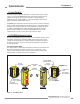
EZ-SCREEN Grid System Introduction Instruction Manual 1. Introduction — Overview 1.1 System Description The Banner EZ-SCREEN™ Grid System is an optically synchronized, microprocessor-controlled, opposed-mode optoelectronic “light grid.” This economical two-part system consists of an emitter and receiver. The system requires no external controller or sync wire between the emitter and receiver; the microprocessors are located within the receiver.
EZ-SCREEN Grid System Introduction Instruction Manual Five sensor configurations are available, with two, three or four beams; emitters have short-range and long-range versions. (Receivers are the same for both long-range and short-range operation.) Beam spacing ranges from 300 mm to 584 mm (12" to 23"), depending on the model. The configuration (the overall length and beam spacing) required for an application is determined by the application and the safety standards being followed. Models SG..
EZ-SCREEN Grid System Introduction Instruction Manual 1.2 Applications and Limitations The Banner EZ-SCREEN Grid System is designed for use in access-guarding and perimeter-guarding applications. It is designed to be mounted vertically, in order to detect a body or torso (rather than a hand or an arm) as a person enters a hazardous area. It is not intended nor designed for hand or finger detection in point-of-operation guarding or for area-guarding applications.
EZ-SCREEN Grid System Introduction Instruction Manual ! WARNING . . . Use of Trip Output Hard Guarding Hard Guarding Application of power to the EZ-SCREEN Grid System MUST NOT initiate dangerous machine motion. Machine control circuitry must be designed so that one or more initiation devices must be engaged (i.e. a conscious act) to start the machine in addition to the EZSCREEN Grid System going into RUN mode.
EZ-SCREEN Grid System Introduction Instruction Manual 1.3 Control Reliability In addition to physical location requirements, safety standards require a safety system such as the EZ-SCREEN Grid to fulfill some internal requirements. For example, for an optical safety system to be used in a Safety Category 4 application (per ISO 13849-1/EN954-1), it must be third-party certified to the type 4 requirements of IEC 61496-1 and -2.
EZ-SCREEN Grid System Introduction Instruction Manual If trip output is selected, the OSSD outputs will turn ON after power is applied, and the receiver passes its internal self-test/synchronization and recognizes that all beams are clear. The trip output will also automatically reset after all interruptions of one or more beams are cleared. If latch output is selected, the EZ-SCREEN requires a manual reset for the OSSD outputs to turn ON, after power is applied and all beams are clear (see Section 4.2.
EZ-SCREEN Grid System Components and Specifications Instruction Manual 2. System Components and Specifications ! 2.1 Models Available Overall Length SGE2-584 Emitter SGR2-584 Receiver SGP2-584 Kit SGXLE2-584 Emitter SGR2-584 Receiver SGXLP2-584 Kit 768 mm (30.
EZ-SCREEN Grid System Components Instruction Manual Lens Shields NOTE: The total range decreases by approximately 10% per shield. Model Part Number Fits EZ-SCREEN Models Length EZS-684 61949 SG..E/R2-500 684 mm EZS-768 61950 SG..E/R2-584 768 mm EZS-984 61951 SG..E/R3-400 984 mm EZS-1251 61952 SG..E/R3-533 1251 mm EZS-1084 61953 SG..E/R4-300 1084 mm Mirrors M6 x 19 mm screw (4 supplied) 101.2 mm (3.98") NOTE: The total range decreases by approximately 8% per mirror.
EZ-SCREEN Grid System Components Instruction Manual MSA Series Stands Part Number Height To Fit Sensor Models MSA-S42-1 43175 42" SG..2-584, SG..2-500 SSM-550, SSM-675 MSA-S66-1 43176 66" SG..3-533, SG..3-400, SG..4-300 SSM-975, SSM-1175 Model To Fit Mirror Models Usable Stand Height Pole 40 mm (1.58") Square NOTE: One EZA-MBK-2 Adaptor Bracket Kit required per sensor (4) M10 Bolt 2.3 Replacement Parts Part Number Model Base Description 6.4 mm (0.
EZ-SCREEN Grid Specifications Instruction Manual 2.5 Specifications EZ-SCREEN Grid System Specifications Supply Voltage (V in) 24V dc ±15%, 10% maximum ripple Emitter: 150 mA max. Receiver: 500 mA max., exclusive of OSSD1 and OSSD2 loads (up to an additional 0.5A each) Short Circuit Protection All inputs and outputs are protected from short circuits to +24V dc or dc common (except Emitter AUX power connections; see Section 3.
EZ-SCREEN Grid Specifications Instruction Manual EZ-SCREEN Grid System Specifications (continued) Effective Aperture Angle (EAA) Meets Type 4 requirements per IEC 61496-2, Section 5.2.9 Short-range models: ± 2.5° @ 3 m Long-range models: ± 2.
EZ-SCREEN Grid Specifications Instruction Manual 12.5 mm (0.50") Minimum Bend Radius 16.7 mm (0.66") See Notes Below EZ-SCREEN Grid EZ-SCREEN Grid BANNER ENGINEERING CORP., USA 888.373.6767 BANNER ENGINEERING CORP., USA 888.373.6767 26 mm (1.02") 107.0 mm (4.21") 52 mm (2.0") 1 2 55 mm (2.1") 1 2 BEAMS BEAMS R E S E T S T A T U S R E S E T S T A T U S L3 L1 L4 L2 25 mm (1.0") 60.0 mm (2.
EZ-SCREEN Grid Installation and Alignment Instruction Manual 3. Installation and Alignment ! Read Section 3 in its entirety before installing the Banner EZ-SCREEN Grid System. The Banner EZ-SCREEN Grid System’s ability to perform its safety guarding function depends upon the appropriateness of the application and upon its proper mechanical and electrical installation and interfacing to the guarded machine.
EZ-SCREEN Grid Installation and Alignment Instruction Manual 3.2 Security Protocol Certain procedures for installing, maintaining and operating the EZ-SCREEN Grid system must be performed by either Designated Persons or Qualified Persons. A Designated Person is identified and designated in writing, by the employer, as being appropriately trained and qualified to perform the specified checkout procedures on the EZ-SCREEN Grid system. A machine operator so designated may be a Designated Person.
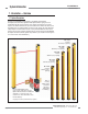
EZ-SCREEN Grid Installation and Alignment Instruction Manual 3.3 Mechanical Installation Considerations Two factors have the greatest influence on the mechanical installation of the EZ-SCREEN System: • The required separation (safety) distance, and • The presence of hard guarding. 3.3.1 Minimum Separation Distance (Ds) Minimum Separation (Safety) Distance (Ds) is the minimum distance required between the light grid and the closest reachable hazard point.
EZ-SCREEN Grid Installation and Alignment Instruction Manual Notice Regarding MPCEs Each of the two Machine Primary Control Elements (MPCE 1 and MPCE2) must be capable of immediately stopping the dangerous machine motion, irrespective of the state of the other. These two channels of machine control need not be identical, but the stop time performance of the machine (Ts, used to calculate the separation distance) must take into account the slower of the two channels.
EZ-SCREEN Grid Installation and Alignment U.S. Applications: Using the formula, Ds = K x (Ts + Tr) + Dpf separation distance for a model SG..3-533 EZ-SCREEN Grid System (42" protected height with 3 beams, 21" apart) is calculated (per ANSI/RIA R15.06): K = 63"/second Ts = 0.32 (0.250 second is specified by the machine manufacturer; plus 20% safety factor; plus 20 ms for interface module IM-T-9A response) Instruction Manual ! CAUTION . . .
EZ-SCREEN Grid Installation and Alignment Instruction Manual ! WARNING . . . The Machine Hazard Must Be Accessible Only Through the Light Grid Mechanical barriers (“hard guarding”) or supplemental safeguarding, as described by the ANSI B11 series of safety requirements or other appropriate standards, must be installed wherever needed to prevent any person from: 3.3.
EZ-SCREEN Grid Installation and Alignment Instruction Manual 3.3.3 Emitter/Receiver Orientation The emitter and receiver must be mounted vertically, and parallel to each other, with their displays either both at the top or both at the bottom. Otherwise dangerous voids in the light grid could allow objects or personnel to pass undetected through the grid (see Figure 3-5).
EZ-SCREEN Grid Installation and Alignment Instruction Manual ! WARNING . . . Avoid Installation Near Reflective Surfaces Avoid mounting the light grid near any reflective surfaces. A reflective surface located nearby may reflect light around an object or person within the light grid, preventing its detection by the light grid. This possibility is detected during the trip test. Failure to prevent reflection problems will result in incomplete guarding; serious bodily injury or death could result. 3.3.
EZ-SCREEN Grid Installation and Alignment Instruction Manual 3.3.5 Use of Corner Mirrors EZ-SCREEN Grid Systems may be used with one or more vertical corner mirrors in perimeter-guarding applications (see Section 2.2 for availability). The use of corner mirrors reduces the maximum specified emitter/receiver separation by approximately 8 percent per mirror (see Section 3.4). Mirrors are not allowed for applications that would allow personnel undetected access into the safeguarded area.
EZ-SCREEN Grid Installation and Alignment Instruction Manual 3.3.6 Avoiding Electrical and Optical Noise The EZ-SCREEN System is designed and manufactured to be highly resistant to electrical and optical noise and to operate reliably in industrial settings. However, extreme electrical and/or optical noise may cause a random trip or latch condition. In very extreme cases, a lockout is possible. Care should be taken to avoid sources of interference when planning the mounting location.
EZ-SCREEN Grid Installation and Alignment Instruction Manual 3.4 Mechanical Mounting Procedure Short-range emitters and receivers may be mounted up to 20 m (65') apart. Long-range emitters and receivers may be mounted between 15 m (49') and 70 m (230') apart. If Banner SSM corner mirrors are used, the total range decreases by approximately 8 percent per mirror, as follows: Corner Mirrors Short-Range Systems Long-Range Systems 1 18.3 m (60') total 64 m (210') total 2 16.8 m (55') total 59.
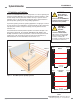
EZ-SCREEN Grid Installation and Alignment Instruction Manual Mounting the Sensors All system components (emitter, receiver, and corner mirrors, if used), must be parallel to each other and perpendicular to the floor. If the floor is level, the components may be checked for plumb, using a level, for example. If the floor is sloped, alignment is more complex, because the floor-to-bottom-beam measurement must remain constant, or not exceed the maximum height above the floor.
EZ-SCREEN Grid Installation and Alignment Instruction Manual Installations With Corner Mirrors If corner mirrors are used in the application, measure and position them as for the sensors. Refer to the data sheet packed with the mirrors for specific installation instructions. ! WARNING . . .
EZ-SCREEN Grid Installation and Alignment Instruction Manual 4) Route the wires or cabling through the bracket (if necessary) and the wiring chamber end cap. Remove outer cable insulation as necessary (approximately 1" to 2") and strip the individual wire insulation approximately 7 mm (0.25"); make connections to terminals as indicated in Figure 3-11. Torque the terminal screws to 0.22 to 0.25 N m (1.9 to 2.2 in. lbs.) recommended torque.
EZ-SCREEN Grid Installation and Alignment Instruction Manual 3.6 Light Grid Initial Checkout and Optical Alignment Procedure Verifying System Operation The initial checkout procedure must be performed by a Qualified Person (see WARNING, page 17). It must be performed only after configuring the System and after connecting the emitter and receiver per Section 3.5.
EZ-SCREEN Grid Installation and Alignment Instruction Manual Optical Alignment Procedure After the emitter and receiver are mechanically aligned (perpendicular to the floor along the path of the beams, and plumb in all possible directions), optically align them, first using the LAT-1, if desired, and finally using the receiver Beam Status indicators. Beam 1 location mark is visible in center of hole Figure 3-12.
EZ-SCREEN Grid Installation and Alignment Instruction Manual 1) Attach the battery-powered LAT-1 to the housing of the emitter over the location of beam 1 (closest to the display), using the EZ-SCREEN bracket clip included with the tool. A dot on the sensor housing next to the lens window indicates the beam’s location. Align the hole on the LAT-1 over the beam 1 marking (see Figure 3-12).
EZ-SCREEN Grid Installation and Alignment Instruction Manual ! WARNING . . . Interfacing of both OSSDs Both of the OSSD (Output Signal Switching Device) outputs must be connected to the machine control so that the machine’s safety-related control system interrupts the circuit to the machine primary control element(s), resulting in a nonhazardous condition.
EZ-SCREEN Grid Installation and Alignment Instruction Manual The interfacing of the Safety Stop Circuits must be accomplished so that the safety function can not be suspended, overridden, or defeated, unless accomplished in a manner at the same or greater degree of safety as the machine’s safety related control system that includes the EZ-SCREEN.
EZ-SCREEN Grid Installation and Alignment Instruction Manual NOTE: MPCE Monitoring and Control Reliability In the U.S., Control Reliability requires that a single failure does not prevent a normal stop from occurring, or issues an immediate stop command, and the next cycle is prevented from occurring until the fault is corrected.
EZ-SCREEN Grid Installation and Alignment Instruction Manual 3.7.4 Remote Test Input A pair of terminals is provided on the emitter terminal block (labeled TEST1 and TEST2) for the connection of an external remote test switch (typically a normally open contact held closed). This remote test input may be useful for EZ-SCREEN Grid System setup and checkout procedures. Opening this switch “turns OFF” the emitter, simulating an interruption of the light beams; all OSSD outputs will turn OFF.
EZ-SCREEN Grid Installation and Alignment Instruction Manual ! WARNING . . . Proper Wiring +24V dc The generalized wiring configurations shown are provided only to illustrate the importance of proper installation. 0V dc EZ-SCREEN Emitter The proper wiring of the EZSCREEN Grid System to any particular machine is solely the responsibility of the installer and end user. PE 1 dc Com 2 +24V dc 3 Open to test (1) TEST2 4 or 1) TEST input must be jumpered if not used.
EZ-SCREEN Grid Installation and Alignment Instruction Manual +24V dc CAUTION. . . 0V dc Shock Hazard Always disconnect all power from the EZ-SCREEN System and the guarded machine before making any connections or replacing any component. Use extreme caution to avoid electrical shock at all times. EZ-SCREEN Receiver PE 1 dc Com 2 +24V dc 3 (Not Used) 4 (1) RESET 5 EDM1 6 Serious bodily injury or death could result.
EZ-SCREEN Grid Installation and Alignment Instruction Manual CAUTION. . . +24V dc 0V dc Shock Hazard Always disconnect all power from the EZ-SCREEN System and the guarded machine before making any connections or replacing any component. Use extreme caution to avoid electrical shock at all times. EZ-SCREEN Receiver dc Com 2 +24V dc 3 (Not Used) 4 Serious bodily injury or death could result. (1) RESET 5 EDM1 6 WARNING . . .
EZ-SCREEN Grid Installation and Alignment Instruction Manual 4. System Operation 4.1 System Configuration Settings System configuration settings are made on the configuration panels located on each sensor, behind the threaded access port cap (use the supplied spanner wrench to remove the cap). See Figure 4.1. After configuration settings are verified/set, the access port cap must be fully re-installed to maintain NEMA/IP ratings.
EZ-SCREEN Grid System Operation Instruction Manual 4.2 Reset Procedures 4.2.1 Receiver Resets The EZ-SCREEN Grid receiver has a RESET input, terminal 5, that allows the System to be manually reset. To reset the receiver, close the Reset switch for 1/4 to 2 seconds, then open the Reset switch. (If Reset switch model MGA-KS0-1, listed in Section 2, is used, close the switch by turning the key 1/4 turn clockwise; open it by turning the key counterclockwise, back to its original position.
EZ-SCREEN Grid System Operation Instruction Manual Receiver: A bi-color red/green Beam Status indicator for each beam shows whether that beam is aligned and clear with a strong signal, clear but with a weak signal, or is blocked and/or misaligned. A yellow Reset indicator shows when the system is in Run mode or is waiting for a reset. A bi-color red/green Status indicator shows when the OSSD outputs are ON (green) or OFF (red), or the system is in lockout mode (flashing red).
EZ-SCREEN Grid System Operation Instruction Manual 4.4 Normal Operation System Power-Up The System will power up in one of two ways, depending on the Trip/Latch output configuration. If the System is set for Trip output, it will power up and reset automatically; if the System is set for Latch output, it will require a manual reset procedure after power-up and sensor alignment.
EZ-SCREEN Grid System Operation Instruction Manual 4.5 Periodic Checkout Requirements To ensure continued reliable operation, the System should be checked out periodically. At every shift change, power-up and machine setup change, the Daily checkout should be performed; this checkout may be performed by a Designated or Qualified Person (see Section 6.4 for the procedure).
EZ-SCREEN Grid System Operation Instruction Manual 5. Troubleshooting and Maintenance Evaluate status indicators per Section 4.3. 5.1 Troubleshooting Lockout Conditions A lockout condition causes all of the EZ-SCREEN OSSD outputs to turn or remain OFF, sending a “stop” signal to the guarded machine. Each sensor provides diagnostic error codes to assist in the identification of the cause(s) of Lockouts (see Figure 5-1). The System provides easy methods for determining operating problems.
EZ-SCREEN Grid Troubleshooting and Maintenance Instruction Manual 5.1.1 Receiver Error Codes Refer to Figure 5-1 for a full description of receiver error codes and what to do when they occur. Diagnostic Display Error Description Appropriate Action Output Error Error is caused by: • one or both outputs being shorted to a power supply (high or low), • by shorting OSSD 1 to OSSD 2, or • by an overload (greater than 0.5A). • Disconnect the OSSD loads and reset the receiver.
EZ-SCREEN Grid Troubleshooting and Maintenance Instruction Manual Diagnostic Display Error Description Appropriate Action DIP Switch Error This error can be caused by incorrect DIP switch settings or by changes to the DIP switch settings when the system is on. • Verify that the DIP switch settings are valid (per Section 4.1). Make any corrections necessary and perform a receiver reset.
EZ-SCREEN Grid Troubleshooting and Maintenance Instruction Manual 5.1.2 Emitter Error Codes NOTE: The emitter flashes the number 2 followed by the other error code digit, pauses, then flashes the sequence again. Diagnostic Display Error Description Cause of Error Test Input Error This error can occur if excessive noise is present on the test input. • Reset the emitter by disconnecting and reapplying power to the emitter (see Section 4.2).
EZ-SCREEN Grid Troubleshooting and Maintenance Instruction Manual ! WARNING . . . Shut Down Machinery before Servicing The machinery connected to the EZ-SCREEN Grid System must not be operating at any time during this procedure. Some servicing procedures may involve working close to the hazardous areas of the guarded machine. Serious bodily injury or death could result. ! CAUTION . . .
EZ-SCREEN Grid Troubleshooting and Maintenance Instruction Manual 5.3 Test Mode Opening a switch or relay contacts connected to the TEST1 and TEST2 terminals of the emitter, or supplying a voltage of less than 3V dc to TEST1 only, simulates a blocked condition, for testing purposes.
EZ-SCREEN Grid Periodic Checkout Procedures Instruction Manual 6. Periodic Checkout Procedures Study each procedure from beginning to end before you start to make sure that you understand each step. Refer all questions to the Banner Applications Engineering Department at the address or numbers listed on the front cover of this manual. Checkouts must be performed as detailed in Section 6.1 below and results should be recorded and kept in the appropriate place (e.g.
EZ-SCREEN Grid Periodic Checkout Procedures Instruction Manual If mirrors are used in the application: Test the grid at three points on each leg of the beam path (emitter to mirror, between mirror and receiver). See Figure 6-2. ! Verify that the appropriate Beam Status indicator turns Green when the blockage is removed from each beam. WARNING . . . If Trip Test Indicates a Problem If the EZ-SCREEN Grid System does not respond properly to the Trip Test, do not attempt to use the System.
EZ-SCREEN Grid Periodic Checkout Procedures Instruction Manual 6.3 Commissioning Checkout Perform this checkout procedure as part of System installation (after the System has been interfaced to the guarded machine as described in Section 3.7), or whenever changes are made to the System (either a new configuration of the EZ-SCREEN System or changes to the machine).
EZ-SCREEN Grid Periodic Checkout Procedures Instruction Manual 8) Observe the receiver 7-segment display to verify that the system is set to the desired operating mode (Trip Output - “–”; Latch - “L”). ! Observe the status indicators on the receiver to determine light grid status: A blocked condition is indicated by the Status indicator steady Red, and one or more Beam Status indicator(s) steady Red. WARNING . . .
EZ-SCREEN Grid Periodic Checkout Procedures Instruction Manual 6.4 Daily Checkout Perform this checkout procedure at every shift change, power-up and machine set-up change. During continuous machine run periods, this checkout must be performed at intervals not to exceed 24 hours. A Designated Person or Qualified Person (as defined in the Safety Glossary) must perform the procedure; checkout results should be recorded and kept on or near the guarded machine, per OSHA 1910.217(e)(1).
EZ-GUARD Grid Periodic Checkout Procedures Instruction Manual 6.5 Semi-Annual Checkout Perform this checkout procedure every six months following System installation. A Qualified Person (as defined in the Safety Glossary) must perform the procedure; checkout results should be recorded and kept on or near the guarded machine, per OSHA 1910.217(e)(1). 1) Perform the commissioning checkout procedure (Section 6.3).
EZ-SCREEN Grid Appendix Instruction Manual EZ-SCREEN Grid Quick-Disconnect Models Short-Range Models (0.
EZ-GUARD Grid Appendix Instruction Manual QD Model Accessories QD Cables Models QDS-315C QDS-325C QDS-350C QDS-3100C QDS-515C QDS-525C QDS-550C QDS-815C QDS-825C QDS-850C Length 5 m (15') 8 m (25') 15 m (50') 30 m (100') 5 m (15') 8 m (25') 15 m (50') 5 m (15') 8 m (25') 15 m (50') Wire Termination 20 Ga 3-pin Mini-style Female connector on one end; cut-to-length. 20 Ga 20 Ga 5-pin Mini-style Female connector on one end; cut-to-length.
EZ-GUARD Grid Appendix Instruction Manual Accessory Bracket Dimensions • Adapter Bracket Kit for MSA Series Stands • Attaches to standard EZA-MBK-1 bracket (included with sensor) • Kit includes 2 adapters EZA-MBK-2 EZA-MBK-3 • Side-Swivel Bracket Kit • Kit includes 2 adapters 22.2 mm (0.87") 4.2 mm (0.17") 30.5 mm (1.20") 21.6 mm (0.85") 12.5 mm (0.49") 17 mm (0.7") Full Radius 25.0 mm (0.98") 12.7 mm (0.50") 19.1 mm (0.75") 22.2 mm (0.88") 16.0 mm (0.63") 101 mm (3.98") 2x Ø 7.0 mm (0.
EZ-SCREEN Grid Safety Glossary Instruction Manual Glossary of Safety Terms Terms shown in italics in the definitions below are themselves defined elsewhere in the glossary. ANSI (American National Standards Institute): An association of industry representatives which develops technical standards, including safety standards. These standards represent a consensus from a variety of industries on good practice and design. ANSI standards relevant to application of the EZ-SCREEN System include ANSI B11.
EZ-SCREEN Grid Instruction Manual Safety Glossary Machine secondary control element (MSCE): A machine control element independent of the Machine Primary Control Element(s) (MPCEs), capable of removing the source of power from the prime mover of the relevant dangerous machine parts. the operation) and removed (after the operation) by the operator. PSDI is defined in OSHA CFR 1910.217. Banner EZ-SCREEN Systems may not be used as PSDI devices on mechanical power presses, per OSHA regulation 29 CFR 1910.217.
EZ-SCREEN Grid Safety Standards Instruction Manual U.S. Application Standards SOURCES ANSI B11 Documents ANSI B11.1 Machine Tools – Mechanical Power Presses – Safety Requirements for Construction, Care, and Use of ANSI B11.2 Hydraulic Power Presses – Safety Requirements for Construction, Care, and Use of ANSI B11.3 Power Press Brakes – Safety Requirements for Construction, Care, and Use of ANSI B11.4 Shears – Safety Requirements for Construction, Care, and Use of ANSI B11.
EZ-SCREEN Grid Safety Standards Instruction Manual SOURCE Underwriters Laboratories Inc. 333 Pfingsten Road Northbrook, IL 60062-2096 Telephone: (847) 272-8800 SOURCE Part of: Code of Federal Regulations Title 29, Parts 1900 to 1910 Superintendent of Documents Government Printing Office P.O. Box 371954 Pittsburgh, PA 15250-7954 Telephone: (202) 512-1800 U.S.
WARRANTY: Banner Engineering Corp. warrants its products to be free from defects for one year. Banner Engineering Corp. will repair or replace, free of charge, any product of its manufacture found to be defective at the time it is returned to the factory during the warranty period. This warranty does not cover damage or liability for the improper application of Banner products. This warranty is in lieu of any other warranty either expressed or implied. Banner Engineering Corp., 9714 Tenth Ave. No.