
User Manual

P/N 133487 7
Banner Engineering Corp. • Minneapolis, U.S.A.
www.bannerengineering.com • Tel: 763.544.3164
Overview
P/N 112852 rev. F 7
Banner Engineering Corp. • Minneapolis, U.S.A.
www.bannerengineering.com • Tel: 763.544.3164
EZ-SCREEN
Instruction Manual
7
Banner Engineering Corp. • Minneapolis, U.S.A.
www.bannerengineering.com • Tel: 763.544.3164
Banner Engineering Corp. • Minneapolis, U.S.A.
www.bannerengineering.com • Tel: 763.544.3164
Components and Specifications
Defined
Area Height
Standard 14 mm Resolution Models
†
0.1 m to 6 m (4" to 20') range
Emitter (8-pin)
†
Receiver
Emitter/Receiver
Pair
†
Number
of Beams
Response
Time (Tr)
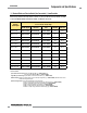
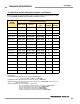
150 mm (5.9") SLSE14-150Q8 SLSR14-150Q8 SLSP14-150Q88 20 11 ms
300 mm (11.8") SLSE14-300Q8 SLSR14-300Q8 SLSP14-300Q88 40 15 ms
450 mm (17.7") SLSE14-450Q8 SLSR14-450Q8 SLSP14-450Q88 60 19 ms
600 mm (23.6") SLSE14-600Q8 SLSR14-600Q8 SLSP14-600Q88 80 23 ms
750 mm (29.5") SLSE14-750Q8 SLSR14-750Q8 SLSP14-750Q88 100 27 ms
900 mm (35.4") SLSE14-900Q8 SLSR14-900Q8 SLSP14-900Q88 120 32 ms
1050 mm (41.3") SLSE14-1050Q8 SLSR14-1050Q8 SLSP14-1050Q88 140 36 ms
1200 mm (47.2") SLSE14-1200Q8 SLSR14-1200Q8 SLS
P14-1200Q88 160 40 ms
1350 mm (53.1") SLSE14-1350Q8 SLSR14-1350Q8 SLSP14-1350Q88 180 43 ms
1500 mm (59") SLSE14-1500Q8 SLSR14-1500Q8 SLSP14-1500Q88 200 48 ms
1650 mm (65") SLSE14-1650Q8 SLSR14-1650Q8 SLSP14-1650Q88 220 52 ms
1800 mm (70.9") SLSE14-1800Q8 SLSR14-1800Q8 SLSP14-1800Q88 240 56 ms
†
Only standard 8-pin QD models are listed; 8-pin emitters/receivers feature “swapable” hookup; see Sections 3.3 and 3.7.
For other models:
5-pin emitters with Test input: Replace suffix “Q8” with “Q5”, (e.g., SLSE14-150Q5), and
for the pair replace “Q88” with “Q85” (e.g., SLSP14-150Q85).
Pigtail QD (8-pin models only): Replace the “Q” in the model number with “P” (e.g., SLSE14-150P8).
ESD-safe models: Add “N” to the model number, prior to the QD option designation (e.g., SLSE14-150NQ8). ESD-safe models are not
available with the
pigtail QD option.
Op tional housing finishes: Prior to the QD designation in the model number,
add “A” for a clear (brushed) anodized aluminum finish, black endcaps (e.g., SLSE14-150AQ8),
add “S” for a nickel-plated (“silver”) finish, black endcaps (e.g., SLSE14-150SQ8),
add “B” for a black painted finish, black endcaps (e.g., SLSE14-150BQ8),
add “W” for a white painted finish, black endcaps (e.g., SLSE14-150WQ8), or
add “SO” for a “safety orange” painted finish, black endcaps (e.g., SLSE14-150SOQ8).
2.1 Standard Emitter and Receiver Models (Non-Cascadeable) – 14 mm Resolution
Order one 8-pin cable for each 8-pin emitter or receiver, or one 5-pin cable for each 5-pin emitter; see Table
2.3. For cascadeable emitter and receiver models, see Sections 7.2 and 7.3.