
User Manual

P/N 133487 43
Banner Engineering Corp. • Minneapolis, U.S.A.
www.bannerengineering.com • Tel: 763.544.3164
Overview
43
Banner Engineering Corp. • Minneapolis, U.S.A.
www.bannerengineering.com • Tel: 763.544.3164
EZ-SCREEN
Instruction Manual
System Operation
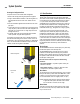
4.4 Status Indicators
A variety of status indicators are clearly visible on each emitter
and receiver front panel (see Figure 1-3 and Section 3.4.1,
steps #3 and #4), and Section 7.7 (cascadeable models only).
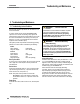
Emitter: A single bi-color Red/Green Status indicator shows
whether power is applied, and whether the emitter is in RUN
mode, optional TEST mode, or Lockout status. A 7-segment
Diagnostic Display indicates a specific error code when the
emitter is in Lockout; the display also momentarily indicates the
Scan Code setting at power-up or when changed.
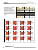
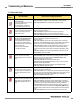
Receiver: Bi-color Red/Green Zone indicators show whether a
section of the defined area is aligned and clear, or is blocked
and/or misaligned. A Yellow Reset indicator shows when the
System is in RUN mode or is waiting for a reset. There are 8
Zone indicat
ors for all model lengths, each of which indicates
Blocked/Clear conditions for approximately 1/8 of the total light
screen.
A bi-color Red/Green Status indicator shows when the OSSD
outputs are ON (Green) or OFF (Red), or the System is in
Lockout status (flashing Red). A 3-digit 7-segment Diagnostic
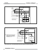
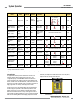
Figure 4-4. Receiver status indicator operation (Trip Output configured)
* NOTE: If beam 1 is blocked, Zone indicators 2-8 will be OFF, because beam 1 provides the synchronization signal for all the beams.
†
Flashing if Reduced Resolution is enabled.
Display indicates the receiver’s Trip (–) or Latch (L) configuration
setting and displays a specific error code when the receiver is in
Lockout. The 7-segment display also momentarily indicates the
Scan Code setting at power-up or when changed.
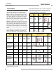
Operating
Status
Required
Event
Status
Indicator
Diagnostic Display
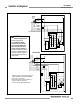
Power-up
Apply
power
Red single-
flash
Scan code flash 3x –
alternates
Run Mode
Passes
internal
tests
Green Dash
Test Mode
Open Test
switch
Flashing
Green
Dash
Lockout
Internal/
external
fault
Flashing
Red
Displays error code (see
Section 5.1)
then
or
then
Figure 4-3. Emitter status indicator operation
Operating
Mode
Required
Event
Reset
Indicator
Status
Indicator
Zone
Indicators*
Diagnostic Displays
OSSD
Outputs
Power-up
Apply
power
OFF
Single-
Flash Red
All Single-
Flash Red
Scan code flash 3x –
alternates
OFF
Alignment Mode –
Beam 1 Blocked
Pass
internal
tests
OFF OFF
Zone 1 Red*
Others OFF
OFF
Alignment Mode –
Beam 1 Clear
Align
Beam 1
ON Red
Zone 1 Green
Others Red or
Green
Total number of blocked beams OFF
Run Mode –
Clear
Align all
beams
ON
ON or
Flashing
Green
†
All ON Green OFF OFF ON
Run Mode –
Blocked
Beam(s)
blocked
ON Red Red or Green* Total number of blocked beams OFF
Noise Detected –
Reset Interface
Flashing
Continues
previous
reading
Continues
previous
reading
Noise Detected –
EDM
Interface
Continues
previous
reading
Continues
previous
reading
Flashing
Lockout
Internal/
external
fault
OFF
Flashing
Red
All OFF Displays error code (see Section 5.1) OFF
then
or
then