
User Manual

P/N 133487 19
Banner Engineering Corp. • Minneapolis, U.S.A.
www.bannerengineering.com • Tel: 763.544.3164
Overview
P/N 112852 rev. F 19
Banner Engineering Corp. • Minneapolis, U.S.A.
www.bannerengineering.com • Tel: 763.544.3164
EZ-SCREEN
Instruction Manual
19
Banner Engineering Corp. • Minneapolis, U.S.A.
www.bannerengineering.com • Tel: 763.544.3164
Banner Engineering Corp. • Minneapolis, U.S.A.
www.bannerengineering.com • Tel: 763.544.3164
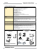
Components and Specifications
50 mm
(1.96")
25 mm
(0.98")
4.2 mm
(0.17")
63.2 mm
(2.49")
Ø 21.5 mm
(0.85")
4 x 5.8 mm (0.23")
wide slots
4 x R 19.4 mm
(0.76")
38.2 mm
(1.50")
Ø 33 mm
(1.30")
4 x 45
20 mm
(0.79")
2 x R 5 mm
(0.20")
2 x 5 mm
(0.20")
2 x 15 mm
(0.59")
2 x 7 mm
(0.28")
20 mm
(0.79")
20 mm
(0.79")
Ø 60 mm
20 mm
(0.79")
17.5 mm
(0.69")
55 mm
(2.17")
50 mm
(1.97")
4.2 mm
(0.17")
55.6 mm
(2.19")
15 mm
(0.59")
20.0 mm
(0.79")
10 mm
(0.39")
9.5 mm
(0.37")
36 mm
(1.42")
Ø 8.3 mm
(0.33")
Ø 7 mm
(0.28")
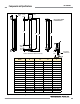
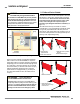
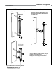
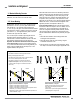
End Cap Brackets
(model EZA-MBK-11*)
Center Bracket
(model EZA-MBK-12**)
Figure 2-1. Included mounting bracket dimensions (for emitter or receiver)
2.7.3 Receiver Specifications, continued
Output Signal Switching Devices
(OSSDs)
Two redundant solid-state 24V dc, 0.5 A max. sourcing OSSD (Output Signal Switching Device) safety
outputs. (Use optional interface modules for ac or larger dc loads.)
Capable of the Banner “Safety Handshake” (see Section 1.1).
ON-State voltage: ≥ Vin-1.5V dc
OFF-State voltage: 1.2V dc max. (0-1.2V dc)
Max. load capacitance: 1.0 µF
Max. load inductance: 10 H
Leakage Current: 0.50 mA maximum
Cable Resistance: 10 Ω maximum
OSSD test pulse width: 100 to 300 microseconds
OSSD test pulse period: 10 ms to 27 ms (varies with number of beams)
Switching Current: 0-0.5 A
Auxiliary (Aux.) Output Switching
Capacity
Current-sourcing (PNP) solid-state output, 24V dc at 75mA max (see Section 3.5.5).
Controls and Adjustments
Scan Code selection: 2-position switch (code 1 or 2). Factory default position is code 1.
Trip/Latch Output selection: Redundant switches. Factory default position is T (trip).
EDM/MPCE monitor selection: 2-position switch selects between 1- or 2-channel monitoring. Factory
default position is 2.
Reduced Resolution: Redundant switches. Factory default position is OFF.
Ambient Light Immunity
> 10,000 lux at 5° angle of incidence
Strobe Light Immunity
Totally immune to one Federal Signal Corp. “Fireball” model FB2PST strobe
Status Indicators
Yellow Reset indicator – indicates whether system is ready for operation or requires a reset
Bi-color (Red/Green) Status indicator – indicates general system and output status
Bi-color (Red/Green) Zone Status indicators – indicate condition (clear or blocked beam) of a
defined group of beams
7-Segment Diagnostic indicator (3 digits) – indicates proper operation, scan code, or error code,
total number of blocked beams
See Figure 1-4 for indicator
locations and Section 4.4 for indicator conditions.
* Dimensions are identical for stainless steel model
EZA-MBK-11N stainless steel brackets for ESD model
emitters and receivers.
** Supplied with emitters
and receivers over 1050 mm.