
User Manual

18 P/N 133487
Banner Engineering Corp. • Minneapolis, U.S.A.
www.bannerengineering.com • T el: 763.544.3164
Overview
18 P/N 112852 rev. F
Banner Engineering Corp. • Minneapolis, U.S.A.
www.bannerengineering.com • T el: 763.544.3164
EZ-SCREEN
Instruction Manual
18
Banner Engineering Corp. • Minneapolis, U.S.A.
www.bannerengineering.com • T el: 763.544.3164
Components and Specifications
Banner Engineering Corp. • Minneapolis, U.S.A.
www.bannerengineering.com • T el: 763.544.3164
Components and Specifications
Supply Voltage at the Device
24V dc ±15% (use a SELV-rated supply according to EN IEC60950)
(The external voltage supply must be capable of buffering brief mains interruptions of 20 ms, as
specified in IEC/EN 60204-1.)
Residual Ripple
± 10% maximum
Supply Current (no load)
275 mA max., exclusive of OSSD1 and OSSD2 loads (up to an additional 0.5A each)
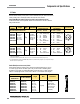
Response Time
Dependent on number of sensing beams (see Section 2.1 for models and number of beams):
10 beams – 9 ms 60 beams – 19 ms 110 beams – 30 ms 160 beams – 40 ms
20 beams – 11 ms 70 beams – 21 ms 120 beams – 32 ms 180 beams – 43 ms
30 beams – 13 ms 80 beams – 23 ms 130 beams – 34 ms 200 beams – 48 ms
40 beams – 15 ms 90 beams – 25 ms 140 beams – 36 ms 220 beams – 52 ms
50 beams – 17 ms 100 beams – 27 ms 150 beams – 38 ms 240 beams – 56 ms
For cascaded systems, also see Section 7.4.
CSSI Response Time
(SLSC.. cascad
e models only)
Response time for a cascade receiver due to opening contacts at the cascade interface (CSSI): 40 ms
max (contacts must open for 60 ms minimum). See Section 7.5.
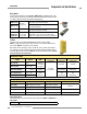
Recovery Time — Blocked to Clear
(OSSDs turn ON; varies with total
number of sensing beams and
whether Sync beam is blocked)
Beam 1 (Sync Beam) All Other Beams
14 mm Models
109 ms to 800 ms 33 ms to 220 ms
30 mm Models
81 ms to 495 ms 25 ms to 152 ms
EDM Input
+24V dc signals from external device contacts can be monitored (one-channel, two-channel or no
monitoring) via EDM1 and EDM2 terminals in the receiver (see Section 3.5.3).
High Signal: 10 to 30V dc at 30 mA typical
Low Signal: 0 to 3V dc
Dropout Time: 200 ms max.
Reset Input
The Reset input must be high for 1/4 to 2 seconds and then low to reset the receiver.
High Signal: 10 to 30V dc at 30 mA typical
Low Signal: 0 to 3V dc
Closed Switch Time: 1/4 to 2 seconds
2.7.3 Receiver Specifications
Supply Voltage at the Device
24V dc ±15% (use a SELV-rated supply according to EN IEC60950)
(The external voltage supply must be capable of buffering brief mains interruptions of 20 ms, as
specified in IEC/EN 60204-1.)
Residual Ripple
± 10% maximum
Supply Current
100 mA max.
Remote Test Input
(Optional – available only on
model SLSE..-..Q5 emitters)
Test mode is activated either by applying a low signal (less than 3V dc) to emitter TEST #1 terminal for a
minimum of 50 milliseconds, or by opening a switch connected between
TEST #1 and TEST #2 for a minimum of 50 milliseconds. Beam scanning stops to simulate a blocked
condition. A high signal at TEST #1 deactivates Test Mode. (See Section 3.5.6 for more information.)
High Signal: 10 to 30V dc
Low Signal: 0 to 3V dc
Input Current: 35 mA inrush, 10 mA max.
Controls and Adjustments
Scan Code Selection: 2-position switch (code 1 or 2). Factory default position is code 1.
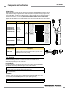
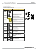
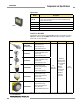
Status Indicators
One bi-color (Red/Green) Status indicator – indicates operating mode, lockout or power OFF
condition
7-Segment Diagnostic indicator (1 digit) – indicates proper operation, scan code, or error code
See Figure 1-4 for indicator locations and Section 4.4 for indicator conditions.
Wavelength of Emitter Elements
Infrared LEDs, 950 nm at peak emission (14 mm) 850 nm at peak emission (30 mm)
2.7.2 Emitter Specifications