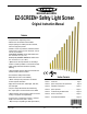
EZ-SCREEN Safety Light Screen ® Original Instruction Manual Features • An optoelectronic safeguarding device • Standard and cascadeable models available • Compact package for smaller production machines, robust for large power presses • Creates a screen of synchronized, modulated infrared sensing beams. Choose from two resolutions, sized in 150 mm (6″) increments: 14 mm (0.55″) resolution models with defined areas from 150 mm to 1.8 m (6″ to 71″) 30 mm (1.
Table of Contents EZ-SCREEN Instruction Manual 1. System Overview . . . . . . . . . . . . . . . . . . . . . . . . . . . . . . . . . . . . . . page 1 1.1 1.2 1.3 1.4 Introduction . . . . . . . . . . . . . . . . . . . . . . . . . . . . . . . . . . . . . . . . . . . . . Applications and Limitations . . . . . . . . . . . . . . . . . . . . . . . . . . . . . . . . Control Reliability: Redundancy and Self-Checking . . . . . . . . . . . . . . Operating Features . . . . . . . . . . . . . . . . . . . . . . .
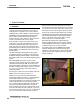
EZ-SCREEN Instruction Manual Overview Overview 1. System Overview 1.1 Introduction The Banner EZ-SCREEN provides a redundant, microprocessorcontrolled, opposed-mode optoelectronic “curtain of light,” or “safety light screen.” It typically is used for point-of-operation safeguarding, and is suited to safeguard a variety of machinery.
Overview 1.2 Applications and Limitations The Banner EZ-SCREEN is intended for point-of-operation machine guarding applications and other safeguarding applications. It is the user’s responsibility to verify whether the safeguarding is appropriate for the application and is installed, as instructed by this manual, by a Qualified Person. Before installing the EZ-SCREEN, read this manual in its entirety, paying particular attention to this section and all of Section 3.
Overview Overview EZ-SCREEN Instruction Manual 1.4 Operating Features The Banner EZ-SCREEN models described by this manual feature several standard selectable functions: • Reduced Resolution (Floating Blanking), • Trip or Latch Output, • External Device Monitoring (EDM), • Auxiliary Output, • Scan Code setting, • Fixed Blanking, • Inverted Display, and • Cascading (available on SLSC.. models).
Overview EZ-SCREEN Instruction Manual 1.4.6 Reduced Resolution (Floating Blanking) Reduced Resolution increases the minimum diameter of an object that the light screen can reliably detect anywhere within its defined area. Reduced Resolution is generally used to allow one or more objects (usually workpiece materials) to move through the defined area, at any point, without tripping the OSSD safety outputs.
Overview Overview EZ-SCREEN Instruction Manual 1.4.8 Manual Resets and Lockout Conditions Reset Routine The EZ-SCREEN requires a manual reset to clear a PowerUp Lockout or Latch condition, and after correcting the cause of a Lockout condition. This function is designed to provide a “monitored manual reset” (i.e., open-closed-open action), such that a shorted or tied-down button cannot cause a reset. When a key-operated switch is used, this is typically called a key reset.
Overview and Components Components andSpecifications Specifications EZ-SCREEN Instruction Manual 2. Components and Specifications An EZ-SCREEN System includes a compatible emitter and receiver (equal length and resolution; available separately or in pairs), and two cables. Mounting hardware is included with each emitter and receiver. Interfacing solutions include IM-T-.. modules, redundant positively guided contactors, or an optional muting module; see Section 2.4.
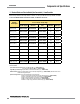
Overview Components and Specifications EZ-SCREEN Instruction Manual 2.1 Standard Emitter and Receiver Models (Non-Cascadeable) – 14 mm Resolution Order one 8-pin cable for each 8-pin emitter or receiver, or one 5-pin cable for each 5-pin emitter; see Table 2.3. For cascadeable emitter and receiver models, see Sections 7.2 and 7.3. Defined Area Height Emitter (8-pin)† Standard 14 mm Resolution Models† 0.
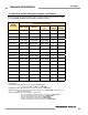
Overview and Components Components andSpecifications Specifications EZ-SCREEN Instruction Manual 2.2 Standard Emitter and Receiver Models (Non-Cascadeable) – 30 mm Resolution Order one 8-pin cable for each 8-pin emitter or receiver, or one 5-pin cable for each 5-pin emitter; see Table 2.3. For cascadeable emitter and receiver models, see Sections 7.2 and 7.3. Defined Area Height Emitter (8-pin)† Standard 30 mm Resolution Models† 0.
Overview Components and Specifications EZ-SCREEN Instruction Manual 2.3 Cables Machine interface cables provide power to the first emitter/receiver pair. Sensor interconnect cables provide power to subsequent emitters and receivers in the cascade. Single-Ended (Machine Interface) Cables (one cable for each emitter and receiver) Overmold and cables are PVC-jacketed. Cables are unterminated on one end to interface with guarded machine.
Overview and Components Components andSpecifications Specifications EZ-SCREEN Instruction Manual Splitter Cordsets Model CSB splitter cordsets allow easy interconnection between an EZ-SCREEN 8-pin receiver and its 8-pin emitter, providing a single “homerun” cable for the optional “swapable” hookup (see Figure 3-16). The model DEE2R-.. double-ended cables described on page 8 may be used to extend the lengths of the QD trunk, branch #1, or branch #2.
Overview Components and Specifications EZ-SCREEN Instruction Manual Muting Modules Provide muting capability for the EZ-SCREEN. (MM-TA-12B is compatible with all 14 mm models 1200 mm and shorter, and with all 30 mm models. See Banner manuals p/n 63517 or 116390 for further information and additional cabling options.) MMD-TA-11B DIN-mount Muting module MMD-TA-12B 2 NO safety outputs (6 amps), 2 or 4 muting inputs, SSI, override input; IP20; terminal connections 2 OSSD (0.
Overview and Components Components andSpecifications Specifications EZ-SCREEN Instruction Manual Lens Shields NOTE: The total sensing range decreases by approximately 10% per shield.
Overview Components and Specifications EZ-SCREEN Instruction Manual MSM Series Corner Mirrors M4 x 10 mm Screw (8 supplied) Rear-surface glass mirrors rated at 85% efficiency. The total sensing range decreases by approximately 8% per mirror. See mirror data sheet P/N 43685 or the Banner Safety catalog for further information. 53.8 mm (2.12") Y L1 L2 50.8 mm (2.00") 72.9 mm (2.87") Defined Area Length Mirror Model Reflective Area Y Mounting L1 Height L2 150 mm (5.9") MSM8A 267 mm (10.
Overview and Components Components andSpecifications Specifications EZ-SCREEN Instruction Manual Accessory Mounting Brackets See Section 2.5 for standard brackets. Contact factory for more information. Order one EZA-MBK-.. bracket per sensor, two per pair. Model EZA-MBK-2 Description Adapter bracket for mounting SSM series mirror to MSA series stands EZA-MBK-20 50.0 mm (1.97") EZA-MBK-20 • Universal adapter bracket for mounting to engineered/slotted aluminum framing (e.g., 80/20™, Unistrut™).
Overview Components and Specifications EZ-SCREEN Instruction Manual Alignment Aids Model LAT-1 Description LAT-1-SS Self-contained visible-beam laser tool for aligning any EZ-SCREEN 14 mm and 30 mm emitter/receiver pair. Includes retroreflective target material and mounting clip. EZA-LAT-SS Replacement adaptor (clip) hardware for SLS..
Overview and Components Components andSpecifications Specifications EZ-SCREEN Instruction Manual 2.
Overview Components and Specifications EZ-SCREEN Instruction Manual 2.7 Specifications 2.7.1 General Specifications Short Circuit Protection All inputs and outputs are protected from short circuits to +24V dc or dc common. Electrical Safety Class (IEC 61140: 1997) III Safety Rating Type 4 per IEC 61496-1, -2; Category 4 PL e, per EN ISO 13849-1; SIL 3 per IEC 61508; SIL CL 3 per IEC 62061 Resolution† and Operating Range Not including blanking 14 mm models: 0.1 m to 6 m (4" to 20') 30 mm models: 0.
Overview and Components Components andSpecifications Specifications EZ-SCREEN Instruction Manual 2.7.2 Emitter Specifications Supply Voltage at the Device 24V dc ±15% (use a SELV-rated supply according to EN IEC60950) (The external voltage supply must be capable of buffering brief mains interruptions of 20 ms, as specified in IEC/EN 60204-1.) Residual Ripple ± 10% maximum Supply Current 100 mA max. Remote Test Input (Optional – available only on model SLSE..-..
Overview Components and Specifications EZ-SCREEN Instruction Manual 2.7.3 Receiver Specifications, continued Output Signal Switching Devices (OSSDs) Two redundant solid-state 24V dc, 0.5 A max. sourcing OSSD (Output Signal Switching Device) safety outputs. (Use optional interface modules for ac or larger dc loads.) Capable of the Banner “Safety Handshake” (see Section 1.1). ON-State voltage: ≥ Vin-1.5V dc OFF-State voltage: 1.2V dc max. (0-1.2V dc) Max. load capacitance: 1.0 µF Max.
Overview and Components Components andSpecifications Specifications 45.2 mm (1.78") EZ-SCREEN Instruction Manual 36.0 mm (1.42") 12 mm* (0.47") See page 19 for detailed bracket dimensions. Y L1 L3 L2 56.0 mm (2.20") 4.2 mm (0.17") 65 mm (2.6") *For SLS..-150 models, this distance is 52 mm (2") Emitter / Receiver Model Housing Length Distance Between Bracket Holes L1 L2 L3 Defined Area† Y SLS..-150 262 mm (10.3") 295 mm (11.6") 237 mm (9.3") 150 mm (5.9") SLS..-300 372 mm (14.
Installation and Overview Alignment EZ-SCREEN Instruction Manual 3. Installation and Alignment Before installing the EZ-SCREEN System, read Section 1.2 and Section 3 of this manual in their entirety. The System’s ability to perform its safety guarding function depends upon the appropriateness of the application and upon its proper mechanical and electrical installation and interfacing to the guarded machine.
Installation Overview and Alignment The formula used for U.S. applications (other standards may apply) to calculate separation distance is: Ds = K x (Ts + Tr) + Dpf where: Ds – the separation distance, in mm (inches); K – 1600 mm per second (or 63" per second), the OSHA1910.217, ANSI B11, ANSI/RIA R15.
EZ-SCREEN Instruction Manual 3.1.2 Pass-Through Hazards A “pass-through hazard” is associated with applications where personnel may pass through a safeguard (which issues a stop command to remove the hazard), and then continues into the guarded area, such as in perimeter guarding. Subsequently, their presence is no longer detected, and the related danger becomes the unexpected start or restart of the machine while personnel are within the guarded area.
Installation Overview and Alignment EZ-SCREEN Instruction Manual 3.1.5 Emitter and Receiver Orientation WARNING . . . The Hazard Must Be Accessible Only through the Defined Area The installation of the EZ-SCREEN must prevent any individual from reaching around, under, over or through the defined area and into the hazard without being detected. Mechanical barriers (e.g.
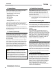
Installation and Overview Alignment EZ-SCREEN Instruction Manual 3.1.6 Adjacent Reflective Surfaces 3.1.7 Use of Corner Mirrors A reflective surface located adjacent to the defined area may deflect one or more beams around an object in the defined area. In the worst case, an “optical short circuit” may occur, allowing an object to pass undetected through the defined area (see Figure 3-6).
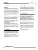
Installation Overview and Alignment EZ-SCREEN Instruction Manual 3.1.8 Installation of Multiple Systems Emitter Whenever two or more EZ-SCREEN emitter and receiver pairs are adjacent to one another, optical crosstalk may potentially take place between systems. To minimize optical crosstalk, alternate the positions of emitters and receivers, (see Figure 3-8a), or alternate Scan Codes.
Installation and Overview Alignment EZ-SCREEN Instruction Manual EZ-SCREEN Mounting Hardware (supplied with each emitter and receiver) End-Mounted Emitters and Receivers 1050 mm and longer also include swivel center bracket Sensors are designed to be mounted with up to 900 mm unsupported distance between brackets (see Section 3.2.1). Bracket Clamp Side-Mounted (Two center brackets may be substituted) NOTES: • EZ-SCREEN sensor brackets are designed to mount directly to MSA Series stands (Section 2.
Installation Overview and Alignment EZ-SCREEN Instruction Manual 3.2 Mechanical Mounting Procedure Once the mechanical layout considerations of Section 3.1 are addressed, mount the sensors and route the cables. 3.2.1 Sensor Mounting Emitter/receiver pairs with 14 mm (0.55") resolution may be spaced from 0.1 m to 6 m (4" to 20') apart. Emitter/receiver pairs with 30 mm (1.18") resolution may be spaced from 0.1 m to 18 m (4" to 60') apart.
Installation and Overview Alignment EZ-SCREEN Instruction Manual 3.2.2 Mounting the Reset Switch 3.3 Initial Electrical Connections Mount the reset switch in a location that complies with the warning in Section 3.1.3. See Section 3.3.2 for electrical connection. 3.2.
Installation Overview and Alignment 3.4 Light Screen Initial Checkout The initial checkout procedure must be performed by a Qualified Person (see Section 4.1). It must be performed only after configuring the System and after connecting the emitter and receiver per Section 3.3. Configuring the System for Initial Checkout Verify that Test input is jumpered (if used) and the System is set to the factory defaults for initial checkout and optical alignment.
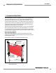
Installation and Overview Alignment EZ-SCREEN Instruction Manual 4. Optical Alignment CAUTION: Ensure that no individuals are exposed to any hazard if the EZ-SCREEN receiver turns ON the OSSD outputs when the System becomes aligned. Straight Edge All OFF Verify sensor mounting per Section 3.2. Straight Edge Verify Optimal Alignment (Rotational Adjustment with power ON) a. Ensure the emitter and receiver are pointed squarely at each other. A straight edge (e.g.
Installation Overview and Alignment EZ-SCREEN Instruction Manual Component #2 (Mirror) Reduced Resolution Setting Maximum Size of Undetected Objects 14 mm Resolution OFF (Not applicable) 14 mm (0.55") ON (2-beam) 8.5 mm (0.34") 30 mm (1.18") 30 mm Resolution OFF (Not applicable) 30 mm (1.18") ON (2-beam) 17 mm (0.67") 60 mm (2.36") Model Component #3 (Mirror) Resulting Resolution WARNING . . .
Installation and Overview Alignment EZ-SCREEN Instruction Manual 8. To teach the blanked beams, simply re-configure DIP switches for normal operation (see Figure 4-1). Verify that only the objects to be blanked are interrupting the defined area. A lockout will occur if an object is moved or removed after teaching. 9.
Installation Overview and Alignment WARNING . . . If Trip Test Indicates a Problem EZ-SCREEN Instruction Manual 3.5 Electrical Interface to the Guarded Machine Permanent Hookup If the EZ-SCREEN System does not respond properly to the trip test, do not attempt to use the System. Make the electrical connections as described in Sections 3.5.1 to 3.5.4 as required by each individual application.
EZ-SCREEN Instruction Manual 3.5.1 OSSD Output Connections Both the Output Signal Switching Device (OSSD) outputs must be connected to the machine control so that the machine’s safety-related control system interrupts the circuit or power to the Machine Primary Control Element(s) (MPCE), resulting in a non-hazardous condition. Final Switching Devices (FSDs) typically accomplish this when the OSSDs go to an OFF state. See Figure 3-21. Refer to the output specifications in Section 2.
Installation Overview and Alignment 3.5.3 Machine Primary Control Elements and EDM Inputs A machine primary control element (MPCE) is an “electrically powered element that directly controls the normal operation of a machine in such a way that it is the last element (in time) to function when machine operation is to be initiated or arrested” (per IEC61496-1). Examples include motor contactors, clutch/ brakes, valves, and solenoids.
Installation and Overview Alignment EZ-SCREEN Instruction Manual Refer to Figure 3-23 for 1-channel EDM hookup. Connect the monitor contacts between +24V dc and EDM1 (pin 3). Leave EDM2 (pin 2) open (no connection). Set the configuration DIP switch to E1, per Section 4.2.
Installation Overview and Alignment EZ-SCREEN Instruction Manual 3.6 Preparing for System Operation 3.7 Sensor “Swapability” and the Optional Emitter Hookup After the initial trip test has been accomplished, the OSSD safety outputs and EDM connections have been made to the machine to be controlled, the EZ-SCREEN is ready for testing in combination with the guarded machine.
EZ-SCREEN Instruction Manual Installation and Overview Alignment +24V dc Receiver 8-pin male Euro-style face view† Bn (Pin #1) +24V dc Gn/Ye (#7) Ground Bu (#6) 0V dc Bk (#5) OSSD1 Wh (#4) OSSD2 Vi (#8) Reset* Or (#3) EDM1 Or/Bk (#2) EDM2 *Trip (auto reset) – Not connected See Table 2.2 for further QDE-8..D cable information. 0V dc FSD 1 FSD 2 Single-Channel Safety Stop Circuit † Dual-Channel Safety Stop Circuit NOTE: Do not exceed OSSD maximum load capacitance specification.
Installation Overview and Alignment EZ-SCREEN Instruction Manual 2-Channel EDM +24V dc Receiver 8-pin male Euro-style face view† 0V dc Bn (Pin #1) Gn/Ye (#7) Bu (#6) Bk (#5) Wh (#4) Vi (#8) Or (#3) Reset** Or/Bk (#2) * Installation of transient (arc) suppressors across the coils of MPCE1 and MPCE2 is recommended (see Warning). IM-T-9A*** S3 ** Trip (auto reset) – Not connected Other interfacing modules and solutions WARNING . . . Use of *** available, see Section 2.
EZ-SCREEN Instruction Manual System Overview Operation 4. System Operation 4.1 Security Protocol Certain procedures for installing, maintaining and operating the EZ-SCREEN system must be performed by either Designated Persons or Qualified Persons. A Designated Person is identified and designated in writing, by the employer, as being appropriately trained and qualified to perform system resets and the specified checkout procedures on the EZ-SCREEN System.
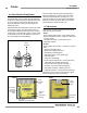
System Operation Overview Accessing the Configuration Panel To open the access cover for DIP switch configuration: 1. Remove the security plate using the special tool supplied. 2. Using a small flat blade screwdriver or the security plate tool, push the plastic tab on the access cover inwards at a 45° angle. 3. Pivot the screwdriver against the bevel until the access cover pops open. 4. To close the access cover, simply push cover into place (it will “snap” into place).
System Overview Operation EZ-SCREEN Instruction Manual 4.4 Status Indicators A variety of status indicators are clearly visible on each emitter and receiver front panel (see Figure 1-3 and Section 3.4.1, steps #3 and #4), and Section 7.7 (cascadeable models only). Display indicates the receiver’s Trip (–) or Latch (L) configuration setting and displays a specific error code when the receiver is in Lockout. The 7-segment display also momentarily indicates the Scan Code setting at power-up or when changed.
System Operation Overview Operating Mode Required Event EZ-SCREEN Instruction Manual Reset Indicator Status Indicator Zone Indicators* OSSD Outputs Diagnostic Displays Scan code flash 3x – alternates Power-up Apply power OFF SingleFlash Red All Single-Flash Red Alignment Mode – Beam 1 Blocked Pass internal tests OFF OFF Zone 1 Red*, Others OFF Alignment Mode – Beam 1 Clear Align Beam 1 ON Red Beam 1 Green, others Red or Green Alignment Mode – All Beams Clear Align all beams DoubleFl
System Overview Operation EZ-SCREEN Instruction Manual Status Indicators for Cascaded Applications When multiple light screens are cascaded, some unique indications may occur, as indicated in Figure 4-7 and in the table at right.
System Operation Overview 4.5 Normal Operation System Power-Up The EZ-SCREEN will power up in one of two ways, depending on the Trip/Latch Output configuration. If it is set for Trip Output, it will power up and reset automatically; if it is set for Latch Output, it will require a manual reset procedure after power-up and sensor alignment.
Troubleshooting and Maintenance Overview EZ-SCREEN Instruction Manual 5. Troubleshooting and Maintenance 5.1 Troubleshooting Lockout Conditions Evaluate status indicators per Section 4.4. See Section 5.2 for Test mode indication. A Lockout condition causes all of the EZ-SCREEN OSSD outputs to turn or remain OFF, sending a stop signal to the guarded machine. Each sensor provides diagnostic error codes to assist in the identification of the cause(s) of lockouts (see Sections 5.1.1 and 5.1.
Troubleshooting and Maintenance Overview EZ-SCREEN Instruction Manual 5.1.1 Receiver Error Codes Diagnostic Display Error Description Cause of Error and Appropriate Action Output Error Error is caused by: • one or both outputs being shorted to a power supply (high or low), • by shorting OSSD 1 to OSSD 2, or • by an overload (greater than 0.5A). • Disconnect the OSSD loads and reset the receiver. • If the error clears, the problem is in the OSSD load(s) or in the load wiring.
Troubleshooting and Maintenance Overview EZ-SCREEN Instruction Manual 5.1.1 Receiver Error Codes (continued) Diagnostic Display Error Description Cause of Error and Appropriate Action EDM 2 Error EDM 2 configuration not valid (wiring or switch). • Verify that the EDM wiring is correct and that the external devices meet the requirements described in Section 3.5.3.
Troubleshooting and Maintenance Overview EZ-SCREEN Instruction Manual 5.1.2 Emitter Error Codes Diagnostic Display* then then Error Description Cause of Error and Appropriate Action Emitter Error This error can occur either due to excessive electrical noise or due to an internal failure. • Reset the emitter by cycling power to the emitter (see Section 4.3.2). • If the error clears, perform a Daily Checkout procedure (Section 6.3) and if OK, resume operation.
Troubleshooting and Maintenance Overview EZ-SCREEN Instruction Manual 5.3 Electrical and Optical Noise 5.4 Servicing and Maintenance Cleaning The EZ-SCREEN is designed and manufactured to be highly resistant to electrical and optical noise and to operate reliably in industrial settings. However, serious electrical and/or optical noise may cause a random Trip or Latch condition. In very extreme electrical noise cases, a Lockout is possible.
Checkout OverviewProcedures EZ-SCREEN Instruction Manual 6. Checkout Procedures Study each procedure in its entirety, to understand each step thoroughly before beginning. Refer all questions to the Banner applications engineering department at the address or numbers listed on the cover of this manual. Checkouts must be performed as detailed in Section 6.1 below and results should be recorded and kept in the appropriate place (e.g., near the machine, and/or in a technical file). 6.
EZ-SCREEN Instruction Manual 9. Observe the Status indicators and the Diagnostic Display: Lockout: • Status flashing Red All others OFF Blocked: • Status ON Red One or more Zone indicators ON Red Reset ON Yellow Clear:• Status ON Green* All Zone indicators ON Green Reset ON Yellow Latch:• Status ON Red All Zone indicators ON Green Reset flashing Yellow (defined area clear) * The Green Status indicator will be flashing if Reduced Resolution is enabled. 10.
Cascadeable Overview EZ-SCREEN EZ-SCREEN Instruction Manual 7. Cascadeable EZ-SCREEN† 7.1 Overview of Cascading 7.1.1 System Components and Specifications EZ-SCREEN emitters and receivers are also available in cascadeable models. These models can be used as standalone light screens, or can be cascaded up to four systems; see Figure 7-1. The cascaded sensor pairs can be any length, any number of beams, or have different resolutions (i.e.
Cascadeable EZ-SCREEN Overview EZ-SCREEN Instruction Manual 7.2 Cascadeable Emitter and Receiver Models – 14 mm Resolution For cabling options, see Section 2.3. Machine interface/power cables (one per end sensor, two per pair): Use QDE-..D cables. Sensor interconnect cables (one per cascaded sensor, two per pair): Use DEE2R-..D cables. Defined Area Height* 14 mm Resolution Cascadeable Models † 0.
Cascadeable Overview EZ-SCREEN EZ-SCREEN Instruction Manual 7.3 Cascadeable Emitter and Receiver Models – 30 mm Resolution For cabling options, see Section 2.3. Machine interface/power cables (one per end sensor, two per pair): Use QDE-..D cables. Sensor interconnect cables (one per cascaded sensor, two per pair): Use DEE2R-..D cables. 30 mm Resolution Cascadeable Models 0.
Cascadeable EZ-SCREEN Overview EZ-SCREEN Instruction Manual 7.4 Determining Interconnect Cable Lengths possible; please call factory for assistance. As the machine interface cable lengthens, the voltage drop increases, which results in shorter possible interconnect cables to maintain supply voltage requirements at the cascaded sensor. See Section 2 for cables. The following cable length charts are possible combinations for each side of example cascaded systems. All cables are assumed to be 22 awg wire.
Cascadeable Overview EZ-SCREEN EZ-SCREEN Instruction Manual Due to the large number of possible combinations, the table in Figure 7-4 includes only applications in which L2 = L4. A common installation example is one that protects two areas of a machine (e.g., the front and back of a power press) and uses four EZ-SCREEN pairs to create two “L”-shaped sensing fields. Machine Interface Cable (L1) QDE-..D 1' 3' 15' 25' Recommended cable pairing per side of cascaded system Individual DEE2R-..
Cascadeable EZ-SCREEN Overview EZ-SCREEN Instruction Manual 7.5 Response Time for Cascaded Light Screens Response time is an important factor in determining a light screen’s separation (safety) distance. For cascaded (or “daisy-chained”) EZ-SCREEN systems, that response time is dependent on the number of light screens, the number of beams in the light screens, and their positions in the cascade.
Cascadeable Overview EZ-SCREEN EZ-SCREEN Instruction Manual Cascade Configuration vs. Response Time When contacts (e.g., an E-stop button) are connected to a cascaded receiver (per Section 7.8), CSSI response time is 40 ms plus the 2 ms adder similar to the defined area Tr. When light screens of different lengths or different resolutions (and therefore different response times) are used in one circuit, their positions in the cascade may become a consideration.
Cascadeable EZ-SCREEN Overview EZ-SCREEN Instruction Manual 7.6 Cascaded Sensor Configuration Settings Setting cascaded sensors for scan code, trip or latch output, external device monitoring (EDM), reduced resolution, fixed blanking and inverted display is identical to the procedure for non-cascadeable emitters and receivers (see Section 4). Scan codes for each emitter and receiver pair must match.
Cascadeable Overview EZ-SCREEN EZ-SCREEN Instruction Manual 7.8 Emergency Stop Buttons and Rope/Cable Pulls Cascadeable EZ-SCREEN receivers may be connected to one or more E-stop buttons. The button(s) must connect to the end of the last receiver in the cascade, in place of the terminator plug. The connected E-stop button(s) will activate/deactivate the OSSD outputs in all receivers in the cascade. The number of E-stop buttons allowed in a series connection is limited by the total resistance per channel.
EZ-SCREEN Instruction Manual 7.9 Positive-Opening Safety Interlock Switches The Cascade input may be used to monitor interlock safety gates or guards. Requirements vary widely for the level of control reliability or safety category (per ISO 13849-1) in the application of interlocked guards.
Cascadeable Overview EZ-SCREEN EZ-SCREEN Instruction Manual Monitoring Series-Connected Positive-Opening Safety Switches When monitoring two individually mounted safety switches (as shown in Figure 7-9), a faulty switch will be detected if it fails to switch as the guard opens. In this case, the EZ-SCREEN will de-energize its OSSD output and disable its reset function until the input requirements are met (i.e., the faulty switch is replaced).
EZ-SCREEN Instruction Manual Glossary Overview Glossary of Terms The following terms are used often in this manual. Where possible, this manual uses definitions from the U.S. and international product performance standards that govern the design of the Safety Controller. For more definitions, visit www.BannerEngineering.com/training/glossary.php.
Glossary Overview Fixed Blanking: A programming feature that allows a safety light screen system to ignore objects (such as brackets or fixtures) which will always be present at a specific location within the defined area. The presence of these objects will not cause the system’s safety outputs (e.g., Final Switching Devices) to trip or latch. If any fixed objects are moved within or removed from the defined area, a Lockout condition results.
EZ-SCREEN Instruction Manual PSDI (Presence-Sensing Device Initiation): An application in which a presence-sensing device is used to actually start the cycle of a machine. In a typical situation, an operator manually positions a part in the machine for the operation. When the operator moves out of the danger area, the presencesensing device starts the machine (no start switch is used). The machine cycle runs to completion, and the operator can then insert a new part and start another cycle.
Notes Overview EZ-SCREEN Instruction Manual Banner Engineering Corp. • Minneapolis, U.S.A. 68 P/N 133487 www.bannerengineering.com • Tel: 763.544.
EZ-SCREEN Instruction Manual Notes Overview Banner Engineering Corp. • Minneapolis, U.S.A. www.bannerengineering.com • Tel: 763.544.
Notes Overview EZ-SCREEN Instruction Manual Banner Engineering Corp. • Minneapolis, U.S.A. 70 P/N 112852 133487 rev. F www.bannerengineering.com • Tel: 763.544.
The list of standards below is included as a convenience for users of this Banner product. Inclusion of the standards below does not imply that the product complies specifically with any standard, other than those specified in the Specifications section of this manual. SOURCES OSHA Documents Superintendent of Documents Government Printing Office P.O. Box 371954 Pittsburgh, PA 15250-7954 Tel: (202) 512-1800 http://www.osha.
Banner Engineering Corp Limited Warranty Banner Engineering Corp. warrants its products to be free from defects in material and workmanship for one year following the date of shipment. Banner Engineering Corp. will repair or replace, free of charge, any product of its manufacture which, at the time it is returned to the factory, is found to have been defective during the warranty period.