
User Manual

P/N 68413 rev. A 27
Banner Engineering Corp. • Minneapolis, U.S.A.
www.bannerengineering.com • Tel: 763.544.3164
EZ-SCREEN Point
Instruction Manual
System Installation
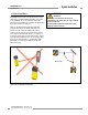
Installations With Corner Mirrors
If corner mirrors are used in the application, measure and
position them as for the sensors. Refer to the data sheet packed
with the mirrors for specific installation instructions.
1. Follow emitter/receiver installation steps 1-3 for installation
without mirrors.
2. Mount the mirror(s) at the desired locations, parallel to the
emitter and receiver. (Use a level to verify plumb, if the floor
surface is level.) Measure up from the floor to position the
center of the mirror’s reflective surface at the vertical center
of the beam grid, using the beam location marks on the
emitter as a guide. Allow additional reflective area above the
top beam and below the bottom beam. Angle the mirror(s)
relative to the sensors, so that one sensor’s front surface can
be seen in the first mirror when standing directly in front of
the other sensor, looking into the mirror.
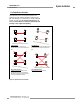
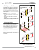
Installations with ACCESS-GUARD Kit
1. Install the supplied Banner MSA series stands and bases per
the instructions supplied with the MSA series stands.
2. Mount the Emitter and Receiver on one stand (using the
supplied mounting brackets) and mount the supplied SSM-
100 mirrors (using the supplied 45° brackets) on the other
stand.
3. Check the floor for level. If the floor is level, check both
stands for plumb. Use the base adjusting bolts, if needed, and
tighten the base mounting bolts.
4. Position the emitter, receiver and mirrors so that the beam
path meets the requirements of the applicable standards. See
Mounting the Sensors and Figure 3-13 on page 29.
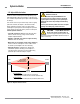
Mounting the Reset Switches
Mount all external Reset switches outside the guarded area,
and out of reach from within the guarded area. The entire
safeguarded area should be visible from the Reset switch
locations. If any areas are not visible, other means must be
used to ensure that no personnel are within the safeguarded
area during the reset (see Warning).
Reset switches must be protected from accidental or
unauthorized operation (e.g., through the use of a key, guards,
or rings).
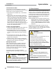
WARNING . . .
Reset Switch Location
Reset switch(es) must be:
• Outside of the hazardous area, in a location that allows the switch
operator full view of the entire guarded area,
• Out of reach from within the safeguarded space, and
• Protected against unauthorized or inadvertent operation.
If any areas are not visible from the Reset switch(es), additional
means of safeguarding must be provided, as described by the ANSI
B11 series or other appropriate standards.
Failure to do so could result in serious injury or death.
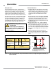
3.5 Electrical Connections
Make the electrical connections in the order described in this
section. It is the user’s responsibility to maintain factory-rated
sealing at all cable access ports in the wiring chamber end cap
of each sensor. One or more of the access ports may be used;
proper wiring entrance hardware (conduit or cable gland) must
be used in each opened access port in order to maintain the
NEMA 4, 13; IEC IP65 rating.
NOTE: EZ-SCREEN wiring is low voltage; running these wires
alongside power wires, motor/servo wires, or other high-
voltage wiring, can inject noise into the EZ-SCREEN
System. It is good wiring practice (and may be required
by code) to isolate EZ-SCREEN System wires from high-
voltage wires.
Wiring barriers in the wiring chamber end caps can accept
individual conductors from #22 to #16 AWG or two conductors
from #22 to #18 AWG. The wires used should have an insulation
temperature rating of at least 90°C (194°F).
WARNING . . .
Proper Electrical
Hookup
• Electrical hookup must be made by Qualified Personnel
and must comply with NEC (National Electrical Code) and local
standards.
• Make no connections to the System other than those
described in Section 3.5 of this manual. Doing so could result
in serious injury or death.
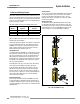
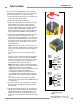
WARNING . . .
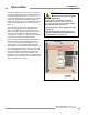
ACCESS-GUARD
Configuration
The ACCESS-GUARD must be properly installed,
e.g. at a beam spacing of 500 mm the range can not exceed 8
meters, to prevent the possibility of misalignment creating voids in
the sensing area or false proxing. See Figure 3-3.