
Safety Light Curtain Systems Owner's manual


50 P/N 133487
Banner Engineering Corp. •Minneapolis, U.S.A.
www.bannerengineering.com•Tel:763.544.3164
Overview
50 P/N 140044 rev. E
Banner Engineering Corp. •Minneapolis, U.S.A.
www.bannerengineering.com•Tel:763.544.3164
EZ-SCREEN LP
Instruction Manual
Troubleshooting and Maintenance
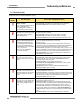
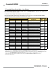
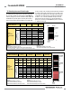
5.1.1 Receiver Error Codes (continued)
Diagnostic
Display
Error Description Cause of Error and Appropriate Action
EDM 2 Error
EDM 2 configuration not valid (wiring or
switch).
•VerifythattheEDMwiringiscorrectandthattheexternaldevicesmeetthe
requirements described in Section 3.5.3.
• If the error continues, remove power to the guarded machine, disconnect the
OSSD loads, disconnect the EDM input signals, configure EDM for no monitoring
(per Section 3.5.3) and conduct the initial checkout procedure (Section 3.4).
• If the error clears, the problem is in the external device contacts or wiring, or is
a response-time problem of the external devices. Verify that the EDM wiring is
correct and that the external devices meet the requirements described in Section
3.5.3.
• If the error continues, check for noise on the EDM inputs (see Section 5.3).
Fixed Blanking Error
This error occurs when beam(s) that
have been blanked (programmed to
ignore a fixed object) become clear
when the object is removed or moved.
•Repositiontheobjectandperformakeyreset(orcyclepower).
•Re-program(teach)thefixedblankedobject(s),seeSections3.4.3and7.10.
Programming Timeout Error
This error occurs when the Fixed
Blanking programming mode (teach)
exceeds the ten-minute limit.
•Re-program(teach)thefixedblankedobject(s),seeSections3.4.3and7.10.
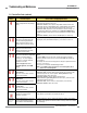
Cascade Configuration Error
This error occurs when the configuration
sequence is incorrectly followed,
receiver(s) 2, 3 or 4 are configured,
or receiver 1 is moved to a different
position in the cascade.
If this code appears for a non-
cascaded application, check EDM
wiring.
•TheCSSIinputchannel(s)areshortedtogetherortoanothersourceofpoweror
ground.
•ConfigureONLY the first receiver in the cascade (connected to the machine
interface). All other receivers must be set for 2-channel EDM and trip output (T),
see Section 7.7.
•Re-configurethefirstreceivertoadaptSystemtochangesorreplacementofother
receivers, see Section 7.7.
•SeeSection7.10forRemoteFixedBlankingprocedures.
NOTE: In a cascaded System, all receivers are connected together, and all
emitters are connected together.
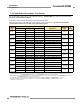
Excessive Noise Error –
Reset Interface
This error can occur due to excessive
levels of electrical noise.
•PerformaresetperSection4.3.
•
If the error clears, perform the daily checkout procedure (per Section 6.3; Daily
Checkout Card) and
if OK, resume operation. If the System fails the Daily
Checkout procedure, replace the receiver.
• If the error continues, check the ground connection (pin 7).
• If the sensor has a good earth ground connection to pin 7, perform the Initial
Checkout procedure (Section 3.4).
• If the error clears, check for sources of electrical noise (see Section 5.3).
•If the error continues, replace the receiver.
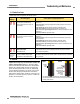
Excessive Noise Error –
EDM Interface
This error can occur due to excessive
levels of electrical noise.
Excessive Noise Error –
Cascade Input
This error can occur due to excessive
levels of electrical noise.
Flashing Cascade Input Simultaneity
Operation of channels A and B
mismatch > 3 seconds.
•CheckoperationofChannelAandChannelBofcascadeinput.
•Cyclepowerorcycletheinput.SeeSections7.8and7.9.
“Axx”/“bxx”,
where “xx” are
alpha-numeric
characters
Advanced Diagnostics for the purpose
of factory troubleshooting and repair;
not intended for field troubleshooting.
If advanced diagnostic codes are inadvertently displayed, toggle the Invert Display
DIP switch (to the opposite state and back, within 1 second) to return to the standard
error code display.