
Safety Light Curtain Systems Owner's manual

44 P/N 133487
Banner Engineering Corp. • Minneapolis, U.S.A.
www.bannerengineering.com • Tel: 763.544.3164
Overview
44 P/N 140044 rev. E
Banner Engineering Corp. • Minneapolis, U.S.A.
www.bannerengineering.com • Tel: 763.544.3164
EZ-SCREEN LP
Instruction Manual
System Operation
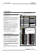
4.4 Status Indicators
A variety of status indicators are clearly visible on each emitter
and receiver face (see Figure 1-3 and Section 3.4.1, steps #3
and #4, and Section 7.7 for cascadeable models).
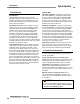
Emitter: A single bi-color Red/Green Status indicator shows
whether power is applied, and whether the emitter is in Run
mode, Test mode, or Lockout status. A 7-segment Diagnostic
Display indicates a specific error code when the emitter is in
Lockout; the display also momentarily indicates the scan code
setting at power-up or when changed.
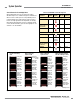
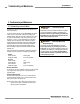
Receiver: Bi-color Red/Green Zone indicators show whether a
section of the defined area is aligned and clear, or is blocked
and/or misaligned. A Yellow Reset indicator shows when the
System is in Run mode or is waiting for a reset. All models
have 8 Zone indicators, each of which indicates Blocked/Clear
conditions for
approximately 1/8 of the total light screen.
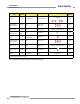
A bi-color Red/Green Status indicator shows when the OSSD
outputs are ON (Green) or OFF (Red), or the System is in
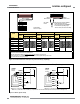
Figure 4-4. Receiver status indicator operation (trip output configured)
Lockout status (flashing Red). A 7-segment Diagnostic Display
indicates the receiver’s trip (–) or latch (L) configuration setting
and displays a specific error code when the receiver is in
Lockout. The 7-segment display also momentarily indicates the
scan code setting at power-up or when changed.
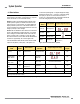
Operating
Status
Status Indicator 7-Segment Diagnostic Display
Power-up Red single-flash
Scan code flash 3x – sequentially
Run Mode Green
Test Mode Flashing Green
Flashing Red
Displays error code
(see Section 5.1)
or
Figure 4-3. Emitter status indicator operation
Operating
Mode
Reset
Indicator
Status Indicator
Zone
Indicators*
7-Segment Diagnostic Display
OSSD
Outputs
Power-up OFF Single-Flash Red All Single-Flash Red
Scan code flash 3x – sequentially
OFF
Alignment Mode –
Beam 1 Blocked
OFF Red
Zone 1 Red*
Others OFF
OFF
Alignment Mode –
Beam 1 Clear
OFF Red Red or Green Total number of blocked beams OFF
Run Mode –
Clear
ON
ON Green or
Flashing Green
†
All ON Green ON
Run Mode –
Blocked
ON Red Red or Green* Total number of blocked beams OFF
Lockout OFF Flashing Red All OFF Displays error code (see Section 5.1) OFF
* NOTE: If beam 1 is blocked, Zone indicators 2-8 will be OFF, because beam 1 provides the synchronization signal for all the beams.
†
Flashing if Reduced Resolution is enabled.
or
Lockout or
Health