
Safety Light Curtain Systems Owner's manual

42 P/N 133487
Banner Engineering Corp. •Minneapolis, U.S.A.
www.bannerengineering.com•Tel:763.544.3164
Overview
42 P/N 140044 rev. E
Banner Engineering Corp. •Minneapolis, U.S.A.
www.bannerengineering.com•Tel:763.544.3164
EZ-SCREEN LP
Instruction Manual
System Operation
4. System Operation
4.1 Security Protocol
Certain procedures for installing, maintaining and operating
the EZ-SCREEN LP must be performed by either Designated
Persons or Qualified Persons.
A Designated Person is identified and designated in writing,
by the employer, as being appropriately trained and qualified to
perform system resets and the specified checkout procedures
on the EZ-SCREEN LP System. The Designated Person is
empoweredto:
•Performmanualresetsandholdpossessionoftheresetkey
(see Section 4.3), and
•Performthedailycheckoutprocedure(seeSection6).
A Qualified Person, by possession of a recognized degree or
certificate of professional training, or by extensive knowledge,
training and experience, has successfully demonstrated the
ability to solve problems relating to the installation of the
EZ-SCREEN LP and its integration with the guarded machine.
In addition to everything for which the Designated Person is
empowered,theQualifiedPersonisempoweredto:
•InstalltheEZ-SCREENLP,
•Performallcheckoutprocedures(seeSection6),
•Makechangestotheinternalconfigurationsettings,and
•ResettheSystemfollowingaLockoutcondition.
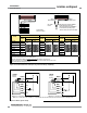
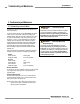
4.2 System Configuration Settings
If not previously configured, System settings are made on the
configuration panels located on each sensor, behind the access
door. The access door is opened by loosening the factory-
installed screw. See Figure 4-1.
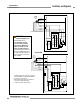
The receiver has redundant Trip/Latch and Reduced Resolution
DIP switches, which must be set identically (see Section 4.2).
Failure to do so will cause a Lockout condition when power is
applied. If the corresponding pairs of DIP switches are not
set identically, the EZ-SCREEN LP will not operate.
Power to the EZ-SCREEN LP receiver should be OFF when
changing DIP switch settings (other than Scan Code) or a
Lockout will occur.
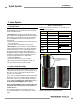
After configuration settings are verified/set, fully close the
access door and tighten the screw to maintain the sensor IP
rating.
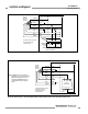
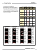
Figure 4-1. Accessing the configuration switches
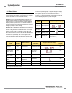
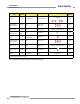
Table 4-1. DIP Switch Settings
Underlined entries indicate factory defaults. “Left” and “right” refer to
positions as shown in Figure 4-1.
Label
Left Position (
←) Right Position (→)
T/L Trip Output Latch Output
RED RES 2-Beam Reduced
Resolution enabled
Reduced Resolution OFF
SCAN Scan Code 2
Scan Code 1
EDM 1-Channel EDM (E1)
2-Channel EDM (E2)
AUX/FLT
Aux (OSSD follow) Fault (lockout)
INVERT Inverted display
OFF (Standard display)
TEST
(Emitter)
Test function
Reset function
FAULT
(Emitter)
ON
OFF
Loosen M2 (Phillips #1) screw,
then rotate hinged door to access
DIP switches
Receiver Emitter