
Safety Light Curtain Systems Owner's manual

40 P/N 133487
Banner Engineering Corp. •Minneapolis, U.S.A.
www.bannerengineering.com•Tel:763.544.3164
Overview
40 P/N 140044 rev. E
Banner Engineering Corp. •Minneapolis, U.S.A.
www.bannerengineering.com•Tel:763.544.3164
EZ-SCREEN LP
Instruction Manual
Installation and Alignment
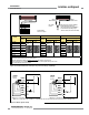
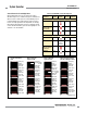
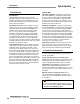
Figure 3-24. Generic hookup – FSDs (2-channel EDM, manual reset)
+24V dc 0V dc
Receiver
8-pin male
Euro-style
face view
†
Bn (Pin #1)
Gn/Ye (#7)
Bu (#6)
Bk (#5)
Wh (#4)
Vi (#8)
Or (#3)
Or/Bk (#2)
+24V dc
Ground
0V dc
OSSD1
OSSD2
Reset*
EDM1
EDM2
FSD
2
FSD
1
Single-Channel
Safety Stop
Circuit
Dual-Channel
Safety Stop
Circuit
NOTE: Do not exceed OSSD maximum load
capacitance specification.
*Trip (auto reset) – Not connected
†
See Table 2.2 for further
QDE-8..D cable information.
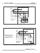
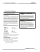
Figure 3-25. Generic hookup – self-checking Safety module, Safety Controller, Safety PLC (no monitoring, automatic reset)
+24V dc 0V dc
Receiver
8-pin male
Euro-style
face view
†
Bn (Pin #1)
Gn/Ye (#7)
Bu (#6)
Bk (#5)
Wh (#4)
Vi (#8)
Or (#3)
Or/Bk (#2)
Jumper
+24V dc
Ground
0V dc
OSSD1
OSSD2
Reset*
EDM1
EDM2
*Trip (auto reset) – Not connected
†
See Table 2.2 for further
QDE-8..D cable information.
S1
A1 A1 A2 A2
S2 S3
SC22-3
Safety Controller
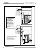
NOTE: EZ-SCREEN LP receiver DIP switches are
configured for “Trip” (T) output and 2-channel
EDM. If the Auxiliary output is to be used,
configure the EZ-SCREEN LP receiver for
1-channel EDM and connect pin #3 (Or) to
+24V dc.
†
See Section 2.3 for further
cordset information.
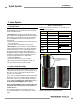
†
See Section 2.3 for further
cordset information.