
Safety Light Curtain Systems Owner's manual


P/N 1334E8 29
Banner Engineering Corp. •Minneapolis, U.S.A.
www.bannerengineering.com•Tel:763.544.3164
Overview
P/N 140044 rev. E 29
Banner Engineering Corp. •Minneapolis, U.S.A.
www.bannerengineering.com•Tel:763.544.3164
EZ-SCREEN LP
Instruction Manual
Installation and Alignment
3.2.2 Mounting the Reset Switch
Mount the reset switch in a location that complies with the warning
in Section 3.1.3. See Figures 3-23 through 3-26 for electrical
connection.
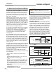
3.2.3 Routing Cables
Attach the required cordsets to the sensors, and route the sensor
cables to the junction box, electrical panel, or other enclosure in
which the interface module, the redundant mechanically linked
interposing relays, FSDs, or other safety-related parts of the
control system are located. This must be done per local wiring
code for low-voltage dc control cables and may require installation
of electrical conduit. See Section 2.3 for selection of Banner-
supplied cables.
NOTE:Themachineinterfacecablemustconnecttothesensor
end adjacent to the indicators, in order for the system to
operate properly.
EZ-SCREEN LP is designed and manufactured to be highly
resistant to electrical noise and to operate reliably in industrial
settings. However, extreme electrical noise may cause a random
Trip or Latch condition; in extreme cases, a Lockout is possible.
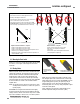
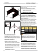
Figure 3-11. Sensor mounting, mechanical alignment
Level Surface
X
Y
Z
Level Surface
X
Emitter Receiver
A B
X
Level Level
Emitter and receiver wiring is low voltage; routing the sensor
wires alongside power wires, motor/servo wires, or other high-
voltage wiring may inject noise into the EZ-SCREEN LP system.
It is good wiring practice (and may be required by code) to
isolate emitter and receiver cables from high-voltage wires,
avoid routing cables close to “noisy” wiring, and provide a good
connection to earth ground.
Sensor cabling and any interconnect wiring should have an
insulation temperature rating of at least 90°C (194°F).
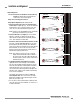
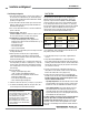
Figure 3-12. RD cordset installation
Verify that:
•Theemitterandreceiveraredirectlyoppositeeachother.
•Nothingisinterruptingthedefinedarea.
•Thedefinedarea(markedonthesensors)isthesamedistance
from a common reference plane for each sensor.
•Theemitterandreceiverareinthesameplaneandarelevel/
plumb and square to each other (vertical, horizontal, or inclined
at the same angle, and not tilted front-to-back or side-to-side).
Angled or Horizontal Installations – verify that:
•DistanceXattheemitterandreceiverareequal.
•DistanceYattheemitterandreceiverareequal.
•DistanceZattheemitterandreceiverareequalfromparallelsurfaces.
•Verticalface(i.e.,thewindow)islevel/plumb.
•Definedareaissquare.Checkdiagonalmeasurementsifpossible;see
Vertical Installations, at right.
Vertical Installations – verify that:
•DistanceXattheemitterandreceiverareequal.
•Bothsensorsarelevel/plumb(checkboththe
side and face).
•Definedareaissquare.Checkdiagonalmeasurementsif
possible (Diagonal A = Diagonal B).
Level
X
Level Surface
Receiver
Emitter
Y
X
Z
B
A
Level Surface
Level
X
Level
2. Tighten Phillips screws at base
of connector to lock into place
1. Slide RD connector
firmly into housing’s
RD port