EZ-SCREEN LP Low-Profile Safety Light Screen ® Instruction Manual Original Instructions Features • A two-piece optoelectronic safeguarding device • C reates a screen of synchronized, modulated infrared sensing beams that extend from end to end of the housing (no “dead” zone) • Low-profile, compact package for smaller production machines, robust for large power presses • Choose standard or cascadeable models • 14 mm or 25 mm resolution; defined areas from 270 to 1810 mm (10.6″ to 71.
Table of Contents 1. Overview . . . . . . . . . . . . . . . . . . . . . . . . . . . . . . . . . . . . . . . . . . . . . . . . . . 1 1.1 1.2 1.3 1.4 Introduction . . . . . . . . . . . . . . . . . . . . . . . . . . . . . . . . . . . . . . . . . . . . . . . . 1 Applications and Limitations . . . . . . . . . . . . . . . . . . . . . . . . . . . . . . . . . . 2 Control Reliability: Redundancy and Self-Checking . . . . . . . . . . . . . . . . . 2 Operating Features . . . . . . . . . . . . . . . . . . . . .
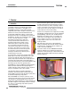
EZ-SCREEN LP Instruction Manual Overview Overview 1. Overview 1.1 Introduction Banner EZ-SCREEN LP emitters and receivers provide a redundant, microprocessor-controlled, opposed-mode optoelectronic “curtain of light,” or “safety light screen.” EZ-SCREEN LP typically is used for point-of-operation safeguarding, and is suited to safeguard a variety of machinery. Emitters have a row of synchronized modulated infrared (invisible) light-emitting diodes (LEDs) in a compact metal housing.
Overview 1.2 Applications and Limitations The Banner EZ-SCREEN LP is intended for point-of-operation machine guarding applications and other safeguarding applications. It is the user’s responsibility to verify whether the safeguarding is appropriate for the application and is installed, as instructed by this manual, by a Qualified Person. Before installing the EZ-SCREEN LP, read this manual in its entirety, paying particular attention to this section and all of Section 3.
EZ-SCREEN LP Instruction Manual 1.4 Operating Features The Banner EZ-SCREEN LP models described by this manual feature several standard selectable functions: • Reduced Resolution (Floating Blanking), • Trip or Latch Output, • External Device Monitoring (EDM), • Auxiliary Output — OSSD Follow or Fault, • Scan Code setting, • Fixed Blanking (including Remote Teach), • Emitter Test and Fault functions, • Inverted Display, and • Cascading (available on SLPC.. models).
EZ-SCREEN LP Instruction Manual Overview 1.4.6 Reduced Resolution (Floating Blanking) Reduced Resolution increases the minimum diameter of an object that the light screen can reliably detect anywhere within its defined area. Reduced Resolution is generally used to allow one or more objects (usually workpiece materials) to move anywhere through the defined area, without tripping the OSSD safety outputs.
EZ-SCREEN LP Instruction Manual 1.4.8 Manual Resets and Lockout Conditions Reset Routine The EZ-SCREEN LP requires a manual reset to clear a PowerUp Lockout or Latch condition, and after correcting the cause of a Lockout condition. This function is designed to provide a “monitored manual reset” (i.e., open-closed-open action), such that a shorted or tied-down button cannot cause a reset. When a key-operated switch is used, this is typically called a key reset.
EZ-SCREEN LP Instruction Manual Overview and Components Components andSpecifications Specifications 2. Components and Specifications An EZ-SCREEN LP “System” refers to a compatible emitter and receiver (equal length and resolution; available separately or in pairs), and cordset(s) for each. It also refers to the emitters and receivers in a cascade, and their cabling.
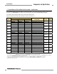
EZ-SCREEN LP Instruction Manual Overview Components and Specifications 2.1 Standard Emitter and Receiver Models (Non-Cascadeable) – 14 mm Resolution For cascadeable emitter and receiver models, see Sections 7.2 and 7.3. Only standard yellow housing models are listed. Pigtail QD models (e.g., SLPE14-270P8) have yellow PVC cable and black PVC QD overmold. For other models, see below.* See the Banner Safety catalog or call the factory for kit model numbering scheme.
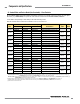
EZ-SCREEN LP Instruction Manual Overview and Components Components andSpecifications Specifications 2.2 Standard Emitter and Receiver Models (Non-Cascadeable) – 25 mm Resolution For cascadeable emitter and receiver models, see Sections 7.2 and 7.3. Only standard yellow housing models are listed. Pigtail QD models (e.g., SLPE25-270P8) have yellow PVC cable and black PVC QD overmold. For other models, see below.* See the Banner Safety catalog or call the factory for kit model numbering scheme.
EZ-SCREEN LP Instruction Manual Overview Components and Specifications 2.3 Cordsets RD to RD Cordsets Machine interface cordsets provide power to the first emitter/ receiver pair. Sensor interconnect cables provide power to subsequent emitters and receivers in the cascade. Only cordsets with yellow PVC cable and black overmolds are listed; for cordsets with black PVC cables and overmolds, add suffix “B” to the model number (e.g., RDLP-815DB).
EZ-SCREEN LP Instruction Manual Overview and Components Components andSpecifications Specifications Euro/M12 QD to Flying Leads Cordsets M12/Euro QD connector on one end; unterminated (cut to length) on other to interface with guarded machine. PVC-jacketed overmold and cables. Model Length Wire For 8-Pin Emitters and Receivers** QDE-815D QDE-825D QDE-830D QDE-850D QDE-875D QDE-8100D 4.5 m (15') 7.6 m (24.9') 9.1 m (30') 15.2 m (49.8') 22.8 m (74.7') 30.4 m (99.
EZ-SCREEN LP Instruction Manual Overview Components and Specifications Bulkhead Connector 3m (9.8') Connector for panel connection of EZ-SCREEN LP emitter and receiver cables. Model PMEF-810D 21.5 mm (0.85") 7.0 mm (0.28") 13.0 mm (0.51") ø 18.0 mm (0.71") Connection 1/4-18NPT 8-pin Euro-style female connector 3 m (10') wires, cut to length (Banner color code); 22 AWG/0.33 mm². M12 x 1 O-Ring 2.4 Accessories Additional interfacing solutions and accessories continue to be added; refer to www.
EZ-SCREEN LP Instruction Manual Overview and Components Components andSpecifications Specifications Muting Modules Provide muting capability for the EZ-SCREEN LP. See Banner manuals p/n 63517 or 116390 for further information and additional cabling options. MMD-TA-11B MMD-TA-12B MM-TA-12B DESE4-508D DESE4-515D DESE4-525D DIN-mount Muting module 2 NO safety outputs (6 amps), 2 or 4 muting inputs, SSI, override input; IP20; terminal connections 2 OSSD (0.
EZ-SCREEN LP Instruction Manual Overview Components and Specifications Alignment Aids Model LAT-1 Description LAT-1-LP Self-contained visible-beam laser tool for aligning any EZ-SCREEN LP emitter/receiver pair. Includes retroreflective target materia, mounting clip.
Overview and Components Components andSpecifications Specifications EZ-SCREEN LP Instruction Manual Accessory Mounting Brackets See Section 2.5 for standard brackets (included with sensors). LPA-MBK-13 • Adaptor for side-mount bracket LPA-MBK-12 • Reorients sensor rotation by 90° (+10°/ −30°) • 14 ga (1.9 mm) steel, black zinc plated • Includes 1 bracket and hardware LPA-MBK-20 • Universal adapter bracket for mounting to engineered/slotted aluminum framing (e.g.
EZ-SCREEN LP Instruction Manual Overview Components and Specifications MSM Series Corner Mirrors M4 x 10 mm Screw (8 supplied) 53.8 mm (2.12") Rear-surface glass mirrors rated at 85% efficiency. The total sensing range decreases by approximately 8% per mirror. See mirror data sheet P/N 43685 or the Banner Safety catalog for further information. Defined Area Length Mirror Model Reflective Area Y Mounting L1 Height L2 270 mm (10.6") MSM12A 356 mm (14") 411 mm (16.2") 381 mm (15") 410 mm (16.
EZ-SCREEN LP Instruction Manual Overview and Components Components andSpecifications Specifications MSA Series Stands (Base Included)* Stand Model Pole Height MSA-S24-1 610 mm (24") MSA-S42-1 1067 mm (42") MSA-S66-1 1676 mm (66") MSA-S84-1 2134 mm (84") Useable Stand Height 483 mm (19") 940 mm (37") 1550 mm (61") 2007 mm (79") MSA-S105-1 2667 mm (105”) 2667 mm (100”) Overall Stand Height 616 mm (24.25") 1073 mm (42.25") 1682 mm (66.25") 2140 mm (84.25") 2673 mm (105.
EZ-SCREEN LP Instruction Manual Overview Components and Specifications 2.7 Specifications 2.7.1 General Specifications Short Circuit Protection All inputs and outputs are protected from short circuits to +24V dc or dc common. Electrical Safety Class (IEC 61140: 1997) III Safety Rating Type 4 per IEC 61496-1, -2; Category 4 PL e per EN ISO13849-1, SIL3 per IEC 61508; SIL CL3 per IEC 62061 Operating Range 0.
EZ-SCREEN LP Instruction Manual Overview and Components Components andSpecifications Specifications 2.7.2 Emitter Specifications Supply Voltage at the Device 24V dc ±15% (use a SELV-rated supply according to EN IEC 60950) (The external voltage supply must be capable of buffering brief mains interruptions of 20 ms, as specified in IEC/EN 60204-1.) Residual Ripple ± 10% maximum Supply Current 60 mA max.
EZ-SCREEN LP Instruction Manual Overview Components and Specifications 2.7.3 Receiver Specifications, continued Output Signal Switching Devices (OSSDs) Two redundant solid-state 24V dc, 0.5 A max. sourcing OSSD (Output Signal Switching Device) safety outputs. (Use optional interface modules for ac or larger dc loads.) Capable of the Banner “Safety Handshake” (see Section 1.1). ON-State voltage: ≥ Vin-1.5V dc OFF-State voltage: 1.2V dc max. (0-1.2V dc) Max. load capacitance: 1.0 µF Max.
EZ-SCREEN LP Instruction Manual Overview and Components Components andSpecifications Specifications 20.0 [0.79"] 10.0 [0.39"] 9.4 [0.37"] L1 L2 26.0 [1.02"] 28.0 [1.10"] L3 R13 mm (0.5") minimum bend See page 19 for detailed bracket dimensions. Emitter / Receiver Model Housing Length L1 Distance Between Bracket Holes L2 L3 Defined Area† SLPE..-270.. 270 mm (10.6") 326 mm (12.8") 258 mm (10.2") 270 mm SLPE..-410.. 410 mm (16.1") 465 mm (18.3") 398 mm (15.7") 410 mm SLPE..-550..
EZ-SCREEN LP Instruction Manual Installation and Overview Alignment 3. Installation and Alignment Before installing the EZ-SCREEN LP, read Section 1.2 and Section 3 of this manual in their entirety. The System’s ability to perform its safety guarding function depends upon the appropriateness of the application and upon its proper mechanical and electrical installation and interfacing to the guarded machine.
EZ-SCREEN LP Instruction Manual Installation Overview and Alignment WARNING . . . Determine Correct Stop Time Stop time (Ts) must include the response time of all devices or controls that react to stop the machine. If all devices are not included, the calculated safety/minimum distance (Ds or S) will be too short. This can lead to serious bodily injury or death. Be sure to include the stop time of all relevant devices and controls in your calculations.
EZ-SCREEN LP Instruction Manual 3.1.2 Pass-Through Hazards A “pass-through hazard” is associated with applications where personnel may pass through a safeguard (which issues a stop command to remove the hazard), and then continues into the guarded area, such as in perimeter guarding. Subsequently, their presence is no longer detected, and the related danger becomes the unexpected start or restart of the machine while personnel are within the guarded area.
EZ-SCREEN LP Instruction Manual Installation Overview and Alignment The mechanical barriers used for this purpose are typically called “hard guarding”; there must be no gaps between the hard guarding and the defined area. Any openings in the hard guarding must comply with the safe opening requirements of ANSI B11 or other appropriate standard. WARNING . . .
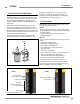
EZ-SCREEN LP Instruction Manual Installation and Overview Alignment 3.1.6 Adjacent Reflective Surfaces A reflective surface adjacent to the defined area may deflect one or more beams around an object in the defined area. In the worst case, an “optical short circuit” may occur, allowing an object to pass undetected through the defined area (see Figure 3-6). This reflective surface may result from shiny surfaces or glossy paint on the machine, the workpiece, the work surface, the floor or the walls.
EZ-SCREEN LP Instruction Manual Installation Overview and Alignment 3.1.7 Use of Corner Mirrors 3.1.8 Installation of Multiple Systems EZ-SCREEN LP may be used with one or more corner mirrors (see Section 2.4).
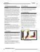
EZ-SCREEN LP Instruction Manual a. Two pairs in a horizontal plane Installation and Overview Alignment 3.2 Mechanical Mounting Procedure Emitter Receiver Once the mechanical layout considerations of Section 3.1 are addressed, mount the sensors and route the cables. Receiver Emitter 3.2.1 Sensor Mounting Emitter/receiver pairs may be spaced from 0.1 m to 7 m (4" to 23') apart. This distance is reduced if corner mirrors are used (see Section 3.1.7).
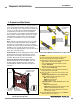
EZ-SCREEN LP Instruction Manual Installation Overview and Alignment Side-Mount Brackets End-Mount Brackets (2 or more* supplied with each emitter and receiver) (2 supplied with each emitter and receiver) Sensors may be mounted with all side-mount brackets, or a combination of side-mount and end-mount brackets. Clamp Bracket −30° rotation +10° rotation 360° Rotation NOTES: • EZ-SCREEN LP sensor brackets are designed to mount directly to MSA Series stands (Section 2.
EZ-SCREEN LP Instruction Manual Installation and Overview Alignment Verify that: • The emitter and receiver are directly opposite each other. • Nothing is interrupting the defined area. • The defined area (marked on the sensors) is the same distance from a common reference plane for each sensor. • The emitter and receiver are in the same plane and are level/ plumb and square to each other (vertical, horizontal, or inclined at the same angle, and not tilted front-to-back or side-to-side).
EZ-SCREEN LP Instruction Manual Installation Overview and Alignment 3.3 Initial Electrical Connections Lockout/tagout procedures may be required (refer to OSHA 29CFR1910.147, ANSI Z244-1, or the appropriate standard for controlling hazardous energy). Following relevant electrical standards and wiring codes, such as the NEC, NFPA79 or IEC60204-1, always connect earth ground (green/yellow wire, see Figures 3-23 through 3-26). Do not operate the EZ-SCREEN LP System without an earth ground connection.
EZ-SCREEN LP Instruction Manual 3.4 Light Screen Initial Checkout The initial checkout procedure must be performed by a Qualified Person (see Section 4.1). It must be performed only after configuring the System and after connecting the emitter and receiver per Section 3.3. Configuring the System for Initial Checkout Verify that the emitter and receiver both are set to the factory defaults for initial checkout and optical alignment.
EZ-SCREEN LP Instruction Manual Installation Overview and Alignment 4. Optical Alignment CAUTION: Ensure that no individuals are exposed to any hazard if the OSSD outputs turn ON when the emitter and receiver become aligned. a. OFF Straight Edge C1 or C2 Straight Edge Verify sensor mounting per Section 3.2. All OFF Verify Optimal Alignment (Rotate with power ON) a. Ensure the emitter and receiver are pointed squarely at each other. A straight edge (e.g.
EZ-SCREEN LP Instruction Manual Installation and Overview Alignment During any adjustments, allow only one individual to adjust only one item at any one time. Component #2 (Mirror) Component #3 (Mirror) NOTE: A LAT-1-LP Laser Alignment Tool is very helpful by providing a visible red dot along the optical axis. See Figure 3-16 and Banner Safety Applications Note SA104 (P/N 57477) for further information. 3.4.
EZ-SCREEN LP Instruction Manual Installation Overview and Alignment Fixed Blanking Configuration 1. From either normal operation or a power OFF condition, set the first and second DIP switches (T/L and Red Res) both to the left (Trip operation and Reduced Resolution enabled positions). See Figure 3-17. 2. Set the third and fourth DIP switches (the second T/L and Red Res) both to the right (Latch operation and Reduced Resolution OFF positions). 3.
EZ-SCREEN LP Instruction Manual Installation and Overview Alignment 3.5 Electrical Interface to the Guarded Machine Test Piece (3 Paths) Emitter Receiver Permanent Hookup Verify that power has been removed from the EZ-SCREEN LP and the guarded machine. Make the electrical connections as described in Sections 3.5.1 to 3.5.5 as required by each individual application. Lockout/tagout procedures may be required (refer to OSHA CFR 1910.
EZ-SCREEN LP Instruction Manual Installation Overview and Alignment 3.5.1 OSSD Output Connections Both the output signal switching device (OSSD) outputs must be connected to the machine control so that the machine’s safety-related control system interrupts the circuit or power to the machine primary control element(s) (MPCE), resulting in a non-hazardous condition. Final switching devices (FSDs) typically accomplish this when the OSSDs go to an OFF state. See Figure 3-24.
EZ-SCREEN LP Instruction Manual Installation and Overview Alignment 3.5.3 Machine Primary Control Elements and EDM Inputs A machine primary control element (MPCE) is an “electrically powered element that directly controls the normal operation of a machine in such a way that it is the last element (in time) to function when machine operation is to be initiated or arrested” (per IEC61496-1). Examples include motor contactors, clutch/ brakes, valves, and solenoids.
EZ-SCREEN LP Instruction Manual Installation Overview and Alignment External Device Monitoring Hookup If not connected previously, it is again strongly recommended that one normally closed, forced-guided monitoring contact of each FSD and MPCE be wired as shown in the monitoring circuit (see Figures 3-24 and 3-26). Pins 2 and 3 of the receiver connector provide connection for the external device monitoring input.
EZ-SCREEN LP Instruction Manual Installation and Overview Alignment Individual Cordsets Splitter Cordsets Pigtail or DELPE.. Cordset RDLP-8..D Cordsets Bn Or/Bk Or Wh Bk Bu Gn/Ye Vi Wire Color (Pin #) CSB.. Splitter Cordset Model CSB.. splitter cordsets and DEE2R.. double-ended cordsets allow easy interconnection between an EZ-SCREEN LP receiver and emitter, providing a single “homerun” cordset (see Section 2.3 Cordsets). See table below or Section 2.
EZ-SCREEN LP Instruction Manual Installation Overview and Alignment +24V dc Receiver 8-pin male Euro-style face view† Bn (Pin #1) +24V dc Gn/Ye (#7) Ground Bu (#6) 0V dc Bk (#5) OSSD1 Wh (#4) OSSD2 Vi (#8) Reset* Or (#3) EDM1 Or/Bk (#2) EDM2 *Trip (auto reset) – Not connected 0V dc FSD 1 FSD 2 Single-Channel Safety Stop Circuit See Section Table 2.22.3forforfurther See further †† cordset QDE-8..Dinformation. cable information.
EZ-SCREEN LP Instruction Manual Installation and Overview Alignment 2-Channel EDM +24V dc Receiver 8-pin male Euro-style face view† 0V dc Bn (Pin #1) Gn/Ye (#7) Bu (#6) Bk (#5) Wh (#4) Vi (#8) Or (#3) Reset** Or/Bk (#2) * Installation of transient (arc) suppressors across the coils of MPCE1 and MPCE2 is recommended (see Warning). IM-T-9A*** S3 ** Trip (auto reset) – Not connected interfacing modules and solutions WARNING . . . Use of *** Other available, see Section 2.
EZ-SCREEN LP Instruction Manual System Operation Overview 4. System Operation 4.1 Security Protocol Certain procedures for installing, maintaining and operating the EZ-SCREEN LP must be performed by either Designated Persons or Qualified Persons. A Designated Person is identified and designated in writing, by the employer, as being appropriately trained and qualified to perform system resets and the specified checkout procedures on the EZ-SCREEN LP System.
EZ-SCREEN LP Instruction Manual Scan code is used to allow operation of multiple pairs of emitters and receivers in close proximity (see Sections 3.1.8 and 1.4.4). Scan code may be set to 1 or 2, via DIP switch (see Table 4-1). The scan code setting for each emitter must agree with its corresponding receiver. Scan code settings may be changed while in Run mode without causing a Lockout. Trip or latch output operation is selected on two DIP switches in the receiver configuration port; see Figure 4-1.
System Operation Overview EZ-SCREEN LP Instruction Manual Lockout status (flashing Red). A 7-segment Diagnostic Display indicates the receiver’s trip (–) or latch (L) configuration setting and displays a specific error code when the receiver is in Lockout. The 7-segment display also momentarily indicates the scan code setting at power-up or when changed. 4.4 Status Indicators A variety of status indicators are clearly visible on each emitter and receiver face (see Figure 1-3 and Section 3.4.
EZ-SCREEN LP Instruction Manual Operating Mode System Overview Operation Reset Indicator Status Indicator Zone Indicators* 7-Segment Diagnostic Display Scan code flash 3x – sequentially OSSD Outputs Power-up OFF Single-Flash Red All Single-Flash Red Alignment Mode – Beam 1 Blocked OFF Red Zone 1 Red* Others OFF Alignment Mode – Beam 1 Clear OFF Red Red or Green Total number of blocked beams OFF Alignment Mode – All Beams Clear DoubleFlash Red All ON Green OFF OFF or OFF OFF Run
EZ-SCREEN LP Instruction Manual System Operation Overview Status Indicators for Cascaded Applications When multiple light screens are cascaded, some unique indications may occur, as indicated in Figure 4-7 and table 4-2.
EZ-SCREEN LP Instruction Manual 4.5 Normal Operation System Power-Up The EZ-SCREEN LP will power up in one of two ways, depending on the trip/latch output configuration. If it is set for trip output, it will power up and reset automatically; if it is set for latch output, it will require a manual reset procedure after power-up and sensor alignment.
Troubleshooting and Maintenance Overview EZ-SCREEN LP Instruction Manual 5. Troubleshooting and Maintenance 5.1 Troubleshooting Lockout Conditions Evaluate status indicators per Section 4.4. See Section 5.2 for Test mode indication. A Lockout condition causes all of the EZ-SCREEN LP’s OSSD outputs to turn or remain OFF, sending a stop signal to the guarded machine. Each sensor provides diagnostic error codes to assist in the identification of the cause(s) of lockouts (see Sections 5.1.1 and 5.1.
EZ-SCREEN LP Instruction Manual Troubleshooting and Maintenance Overview 5.1.1 Receiver Error Codes Multiple-digit codes are sequential, followed by a pause. Diagnostic Display Error Description Cause of Error and Appropriate Action Output Error Error is caused by: • one or both outputs being shorted to a power supply (high or low), • by shorting OSSD 1 to OSSD 2, or • by an overload (greater than 0.5A). • Disconnect the OSSD loads and reset the receiver.
Troubleshooting and Maintenance Overview EZ-SCREEN LP Instruction Manual 5.1.1 Receiver Error Codes (continued) Diagnostic Display Error Description Cause of Error and Appropriate Action DM 2 Error E EDM 2 configuration not valid (wiring or switch). • Verify that the EDM wiring is correct and that the external devices meet the requirements described in Section 3.5.3.
Troubleshooting and Maintenance Overview EZ-SCREEN LP Instruction Manual 5.1.2 Emitter Error Codes Multiple-digit codes are sequential, followed by a pause. Diagnostic Display* “Axx”/“cxx”, where “xx” are alpha-numeric characters Error Description Cause of Error and Appropriate Action Emitter Error This error can occur either due to excessive electrical noise or due to an internal failure. • Reset the emitter by either performing a reset or cycling power to the emitter (see Section 4.3).
5.2 Test Mode (continued) Supply Voltage 10 to 30V dc Opening a switch or relay contacts connected to the emitter Test connections, or supplying a voltage of less than 3V dc to Test only, simulates a Blocked condition, for testing purposes. To verify proper operation, measure the voltage between emitter Test (pin 8, violet) and dc COM (pin 6, blue) and refer to the following table: Troubleshooting and Maintenance Overview 5.
EZ-SCREEN LP Instruction Manual Checkout Procedures Overview 6. Checkout Procedures Study each procedure in its entirety, to understand each step thoroughly before beginning. Refer all questions to a Banner applications engineer at the address or numbers listed on the cover of this manual. Checkouts must be performed as detailed in Section 6.1 below and results should be recorded and kept in the appropriate place (e.g., near the machine, and/or in a technical file). 6.
EZ-SCREEN LP Instruction Manual Checkout OverviewProcedures 9. Observe the Status indicators and the Diagnostic Display: • Lockout: Status flashing Red All others OFF • Blocked: Status ON Red One or more Zone indicators ON Red Reset ON Yellow • Clear: Status ON Green* All Zone indicators ON Green** Reset ON Yellow • Latch: Status ON Red All Zone indicators ON Green Reset flashing Yellow (defined area clear) * The Status indicator will be flashing Green if reduced resolution is enabled.
EZ-SCREEN LP Instruction Manual Cascadeable EZ-SCREEN Overview 7. Cascadeable EZ-SCREEN LP 7.1 Overview of Cascading EZ-SCREEN LP emitters and receivers are also available in cascadeable models. These models can be used as stand-alone light screens, or can be cascaded up to four pairs in one system; see Figure 7-1. The cascaded sensor pairs can be any length, any number of beams, or have different resolutions (i.e., 14 mm and 25 mm), as long as each emitter matches its own receiver. NOTE: EZ-SCREEN SLP..
EZ-SCREEN LP Instruction Manual Cascadeable Overview EZ-SCREEN 7.2 Cascadeable Emitter and Receiver Models – 14 mm Resolution Only standard yellow housing models are listed. Pigtail QD models (e.g., SLPCE14-270P8) have yellow PVC cable and black PVC QD overmold. For other models, see below.* See the Banner Safety catalog or call the factory for kit model numbering scheme. Order one machine interface cordset for each “master” emitter or receiver; see Section 2.3.
EZ-SCREEN LP Instruction Manual Cascadeable EZ-SCREEN Overview 7.3 Cascadeable Emitter and Receiver Models – 25 mm Resolution Only standard yellow housing models are listed. Pigtail QD models (e.g., SLPCE14-270P8) have yellow PVC cable and black PVC QD overmold. For other models, see below.* See the Banner Safety catalog or call the factory for kit model numbering scheme. Order one machine interface cordset for each “master” emitter or receiver; see Section 2.3.
EZ-SCREEN LP Instruction Manual Cascadeable Overview EZ-SCREEN 7.4 Determining Interconnect Cordset Lengths The following Cordset length charts are possible combinations for each side of example cascaded systems. Model DELP-..E cordsets (24 awg wire) used for calculations. Other lengths and combinations are possible; please call factory for assistance. As the machine interface Cordset lengthens, the voltage drop Machine Interface Cordset (L1) QDE-8..D or RDLP-8..D 0.9 m (3') 4.
EZ-SCREEN LP Instruction Manual Cascadeable EZ-SCREEN Overview Machine Interface Cordset (L1) QDE-8..D or RDLP-8..D 0.9 m (3') 4.6 m (15') Emitters 7.6 m (25') Receivers EZ-SCREEN LP Position #4 Example Cordset pairing per side of cascaded system Sensor Interconnect Cordset Lengths (L2, L3 and L4) Individual DELP-11..E Cordsets Max. L3* L2 L3 L4 L2 L3 L4 L2 L3 L4 0.3 m (1') 28 m (92') 0.3 m (1') 0.3 m (1') 20.4 m (67') 0.3 m (1') 0.3 m (1') 13.7 m (45') 0.3 m (1') 15.
EZ-SCREEN LP Instruction Manual Cascadeable Overview EZ-SCREEN Individual Response Time and Safety (Minimum) Distance When calculating individual safety (minimum) distance for each emitter/receiver pair, the pair’s position in the cascade impacts its response time, which then impacts its safety distance (see safety distance formulas in Section 3.1.1).
EZ-SCREEN LP Instruction Manual Emitters Cascadeable EZ-SCREEN Overview Receivers Emitters EZ-SCREEN LP Position #3 Receivers Emitters Receivers EZ-SCREEN LP Position #3 EZ-SCREEN LP Position #3 13.5 + 2 + 2 = 17.5 13.5 + 2 + 2 = 17.5 Individual Response Time: 17.5 ms Individual Response Time: 17.5 ms 43.5 + 2 + 2 = 47.5 EZ-SCREEN LP Position #2 Individual Response Time: 47.5 ms 13.5 + 2 = 15.5 Individual Response Time: 15.5 ms EZ-SCREEN LP Position #2 43.5 + 2 = 45.
EZ-SCREEN LP Instruction Manual Cascadeable Overview EZ-SCREEN 7.7 Configuration for Cascaded Operation Each cascaded system must be configured, before it can be run in a production environment. Before configuration, install all emitters and receivers per Sections 3 and 7. The last SLPCR-.. receiver must be terminated either with a terminator plug, or with an EZARBK-1 remote key switch box, or by connecting two closed mechanical contacts (see Sections 7.8 and 7.9).
EZ-SCREEN LP Instruction Manual Cascadeable EZ-SCREEN Overview E-Stop Switch Requirements (Positive-Opening) As shown in Figure 7-8, the E-stop switch must provide two contact pairs, which are closed when the switch is in the “armed” position. Once activated, the E-stop switch must open its contacts and return to the closed-contact position only after deliberate action (such as twisting, pulling, or unlocking). The switch should be a “positive-opening type,” as described by IEC947-5-1.
EZ-SCREEN LP Instruction Manual Cascadeable Overview EZ-SCREEN 7.9 Positive-Opening Safety Interlock Switches The Cascade input may be used to monitor interlock safety gates or guards. Requirements vary widely for the level of control reliability or safety category (per ISO 13849-1) in the application of interlocked guards.
EZ-SCREEN LP Instruction Manual Cascadeable EZ-SCREEN Overview Monitoring Series-Connected Positive-Opening Safety Switches no longer redundant and, if the second switch fails, may result in an unsafe condition (i.e., the accumulation of faults results When monitoring two individually mounted safety switches (as in the loss of the safety function). shown in Figure 7-9), a faulty switch will be detected if it fails to switch as the guard opens. In this case, the EZ-SCREEN LP 2.
EZ-SCREEN LP Instruction Manual Cascadeable Overview EZ-SCREEN 7.10 Remote Fixed Blanking As described in Sections 1.4.9 and 3.4.3, fixed blanking is available to, in effect, “disable” beams that would otherwise be continually blocked by a stationary object. One or multiple areas within an EZ-SCREEN LP sensor pair may be “blanked out,” with a minimum of one beam between two blanked areas.
EZ-SCREEN LP Instruction Manual Cascadeable EZ-SCREEN Overview Remote Fixed Blanking Programming Procedures Prior to performing these procedures, install the EZ-SCREEN LP per Section 3 of this document, including all other DIP switch configuration settings (T/L, RR, and Scan Code). Align the E/R pair and perform all required checkout procedures to ensure proper operation.
EZ-SCREEN LP Instruction Manual Cascadeable Overview EZ-SCREEN To change (relocate) or clear (remove) previous fixed blanking, when: • Obstruction is relocated or cleared with EZ-SCREEN LP power OFF. • Clearing an Error Code 10 “Fixed Blanking Error” (begin at step #5, with the programming key switch in the Run position) • Clearing an Error Code 12 “Timeout Expired” (begin at step #6, with the programming key switch in the Program position) Action Indication Comments 1 Remove power from EZ-SCREEN LP.
EZ-SCREEN LP Instruction Manual Appendix OverviewA Appendix A. Bracket Assembly Instructions The screwdriver provided with the EZ-SCREEN LP is intended for access to the DIP switches and for preassembly of the mounting brackets. Final assembly (tightening) of the mounting bracket should be accomplished with a #1 Phillips screwdriver or 3/16″ / 5 mm “thin-walled” nut driver to achieve the listed torque specifications.
Glossary Overview EZ-SCREEN LP Instruction Manual Glossary of Terms The following terms are used often in this manual. Where possible, this manual uses definitions from the U.S. and international product performance standards that govern the design of the Safety Controller. For more definitions, visit www.BannerEngineering.com/training/glossary.php. CSA: Abbreviation for Canadian Standards Association, a testing agency similar to Underwriters Laboratories, Inc. (UL) in the United States.
EZ-SCREEN LP Instruction Manual FMEA (Failure Mode and Effects Analysis): A testing procedure by which potential failure modes in a system are analyzed to determine their results or effects on the system. Component failure modes that produce either no effect or a Lockout condition are permitted; failures which cause an unsafe condition (a failure to danger) are not. Banner safety products are extensively FMEA tested. Guarded Machine: The machine whose point of operation is guarded by the safety system.
Glossary Overview PSDI (Presence-Sensing Device Initiation): An application in which a presence-sensing device is used to actually start the cycle of a machine. In a typical situation, an operator manually positions a part in the machine for the operation. When the operator moves out of the danger area, the presencesensing device starts the machine (no start switch is used). The machine cycle runs to completion, and the operator can then insert a new part and start another cycle.
The list of standards below is included as a convenience for users of this Banner product. Inclusion of the standards below does not imply that the product complies specifically with any standard, other than those specified in the Specifications section of this manual. SOURCES OSHA Documents Superintendent of Documents Government Printing Office P.O. Box 371954 Pittsburgh, PA 15250-7954 Tel: (202) 512-1800 http://www.osha.
EC Declaration of Conformity Banner Engineering Corp. 9714 Tenth Avenue North Minneapolis, MN 55441-5019 USA We herewith declare that EZ-SCREEN LP low-profile light screen for industrial control is in conformity with the provisions of the Machinery Directive (Directive 98/37/EEC and 2006/42/EC), and all essential Health and Safety Requirements have been met. 12/02/2009 R. Eagle / Engineering Manager Date Peter Mertens / Managing Director Banner Engineering Corp.