
Instruction Manual


P/N 130426 Rev. C 43
Banner Engineering Corp. •Minneapolis, U.S.A.
www.bannerengineering.com•Tel:763.544.3164
A-GAGE EZ-ARRAY
Instruction Manual
Appendix
Otherwise, the Channel States data can be accessed after every
third scan (default). To set the EZ-ARRAY in Extended Cache
Mode, the register at address 41002 must be set to a value of 1.
This is a configuration register (Communications Configuration),
so this register only needs to be set once. To exit Extended
Cache Mode, the register must be set to a value of 0.
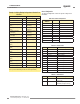
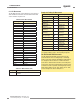
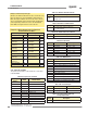
Example A–10. Writing Communications Conguration to
Enable Extended Cache Mode
Request Response
Field Name (Hex) Field Name (Hex)
Slave Address 41 Slave Address 41
Function 10 Function 10
Starting Address
(HIGH Byte)
A0
Starting Address
(HIGH Byte)
A0
Starting Address
(LOW Byte)
2A
Starting Address
(LOW Byte)
2A
Quantity of Registers
(HIGH Byte)
00
Quantity of Registers
(HIGH Byte)
00
Quantity of Registers
(LOW Byte)
01
Quantity of Registers
(LOW Byte)
01
Quantity of Bytes 02 CRC (LOW Byte) 32
Register 41002
(HIGH Byte)
00 CRC (HIGH Byte) 65
Register 41002
(LOW Byte)
01
CRC (LOW Byte) F1
CRC (HIGH Byte) 93
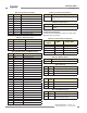
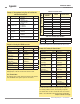
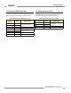
A.3.4 System Info and Status
The System Info and Status section contains the current status
of the EZ-ARRAY.
Table A–40. System Info and Status
Input Register
Address
MASK Member Name
30026 Number of Emitter Channels
30027
Emitter First Bad Channel
30028
Number of Receiver Channels
30029
RESERVED
30030 LOW BYTE DIP Switch
30030 HIGH BYTE ERROR Code
30031 LOW BYTE RESERVED
30031 HIGH BYTE Discrete Outputs
30032
Analog Output 1 DAC
30033
Analog Output 2 DAC
30034
RESERVED
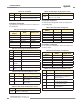
Table A–41. Number of Emitter Channels
Range Description
30-480
Number of channels the emitter has
(multiples of 30)
Table A–42. Emitter First Bad Channel
Range Description
0-480
First channel that emitter is unable to fire
(0 = no bad channels)
Table A–43. Number of Receiver Channels
Range Description
30-480 Number of Receiver channels (multiples of 30)
Table A–44. DIP Switch
Bit Function Description
0 DIP Switch 6 0 = ON, 1 = OFF
1 DIP Switch 5 0 = ON, 1 = OFF
2 DIP Switch 4 0 = ON, 1 = OFF
3 DIP Switch 3 0 = ON, 1 = OFF
4 DIP Switch 2 0 = ON, 1 = OFF
5 DIP Switch 1 0 = ON, 1 = OFF
Table A–45. ERROR Code
Value Status
0 System OK
1 Receiver EEPROM Hard Failure
2 Receiver Alignment/Blanking Configuration Error
3 Reserved for Factory 3
4 Emitter or Wiring Problem
5 Emitter Channel Error
6 Reserved For Factory 6
7 Reserved For Factory 7
8 Reserved For Factory 8
9 Reserved For Factory 9
10 Incompatible Scan and Measurement Mode
Table A–46. Discrete Outputs
Bit Function Description
0 Discrete Output 1 0 = OFF, 1 = ON
1 Discrete Output 2 0 = OFF, 1 = ON
Table A–47. Analog Output 1 DAC and
Analog Output 2 DAC
Range Description
0-4095 Current DAC value of analog output
Example continued from previous page