
Instruction Manual


42 P/N 130426 Rev. C
Banner Engineering Corp. •Minneapolis, U.S.A.
www.bannerengineering.com•Tel:763.544.3164
A-GAGE EZ-ARRAY
Instruction Manual
Appendix
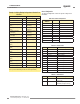
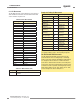
Example A–7. Analog Output Cong Flags for Peak Detection
with External Comm Reset
Bit Flag Description Value
0 Slope
0 = Negative
1 = Positive
X*
1 Measurement
0 = Measurement 2
1 = Measurement 1
X
2
ZERO Value
00 = Hold
01 = Minimum
10 = Maximum
XX
3
4 Peak Detect 0 = Disabled, 1 = Enabled 1
5
Peak Detect
Direction
0 = Maximum
1 = Minimum
X
6 Status
0 = Disabled
1 = Enabled
1
7
Peak Detect
Reset
0 = Auto
1 = External Communications
1
* “X” denotes a “don’t care” value.
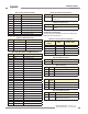
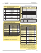
Example A–8. Reading A01 PEAK Measurement
Request Response
Field Name (Hex) Field Name (Hex)
Slave Address 41 Slave Address 41
Function 04 Function 04
Starting Address
(HIGH Byte)
77 Byte Count 02
Starting Address
(LOW Byte)
39
Register 30521
(HIGH Byte)
00
Quantity of Registers
(HIGH Byte)
00
Register 30521
(LOW Byte)
A0
Quantity of Registers
(LOW Byte)
01 CRC (LOW Byte) B8
CRC (LOW Byte) F4 CRC (HIGH Byte) 87
CRC (HIGH Byte) B3
This input register request will read the current Peak value of
Analog Output 1, and will reset the value all in one action.
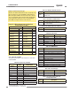
A.3.3 Channel States
The Channel States section contains the state of all the channels
in the EZ-ARRAY. Each register represents 16 channels.
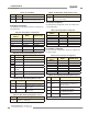
Table A–38. Channel States
Model
Input Register
Address
MASK Member Name
150–1800 mm
30003 LOW BYTE Channel 1-8
30003 HIGH BYTE Channel 9-16
… … …
30025 LOW BYTE Channel 353-360
30025 HIGH BYTE (pad byte)
2100–2400 mm
30003 LOW BYTE Channel 1-8
30003 HIGH BYTE Channel 9-16
… … …
30025 LOW BYTE Channel 349-364
30025 HIGH BYTE Channel 365-380
Table A–39. Channel States Bit-Mask
Value State Description
0 Made The channel is made (clear)
1 Blocked The channel is blocked
For example, if the first and third beams of the EZ-ARRAY are
blocked, input register 30003 would contain the value 0x0005.
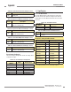
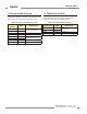
Example A–9. Reading ALL Channel States
Request Response
Field Name (Hex) Field Name (Hex)
Slave Address 41 Slave Address 41
Function 04 Function 04
Starting Address
(HIGH Byte)
75 Byte Count 32
Starting Address
(LOW Byte)
33
Register 30003
(HIGH Byte)
00
Quantity of Registers
(HIGH Byte)
00
Register 30003
(LOW Byte)
00
Quantity of Registers
(LOW Byte)
17
Register 30004
(HIGH Byte)
00
CRC (LOW Byte) 54 00
CRC (HIGH Byte) C7 … …
… …
Register 30025
(HIGH Byte)
00
Register 30025
(LOW Byte)
00
CRC (LOW Byte) 43
CRC (HIGH Byte) B6
To read ALL Channel States, a read input registers request is
sent starting at address 30003, and requesting 23 registers.
The channel states can be accessed after each scan, if Cache
Mode is set to Extended in the Communications Configuration.
Example continued on next page