
Instruction Manual


P/N 130426 Rev. C 41
Banner Engineering Corp. •Minneapolis, U.S.A.
www.bannerengineering.com•Tel:763.544.3164
A-GAGE EZ-ARRAY
Instruction Manual
Appendix
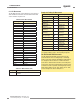
A.3.2 ALL Measurements
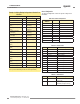
The ALL Measurements section contains the current values of
all the available measurements. The ALL Measurements data
can be read after every third scan.
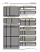
Table A–36. ALL Measurements
Input Registers Member Name
30500 FBB
30501 LBB
30502 TBB
30503 TRN
30504 CBB
30505 FBM
30506 LBM
30507 TBM
30508 CBM
30509 MBB
30510 OD
30511 ID
30512 CFBB
30513 CLBB
30514 O1 FBB
30515 O1 LBB
30516 O2 FBB
30517 O2 LBB
30518 O3 FBB
30519 O3 LBB
30520 CARPET NAP
30521 AO1 PEAK
30522 AO2 PEAK
30523 CARPET EDGE
30524 SPECIAL
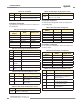
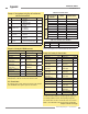
Table A–37. Measurements (ALL)
Range Description
0-1920
Measurements are represented in 4x channel
resolution
Example A–6. Reading ALL Measurements
Request Response
Field Name (Hex) Field Name (Hex)
Slave Address 41 Slave Address 41
Function 04 Function 04
Starting Address
(HIGH Byte)
77 Byte Count 32
Starting Address
(LOW Byte)
24
Register 30500
(HIGH Byte)
00
Quantity of Registers
(HIGH Byte)
00
Register 30500
(LOW Byte)
00
Quantity of Registers
(LOW Byte)
19
Register 30501
(HIGH Byte)
00
CRC (LOW Byte) 64
Register 30501
(LOW Byte)
00
CRC (HIGH Byte) BF … …
… …
Register 30524
(HIGH Byte)
00
Register 30524
(LOW Byte)
00
CRC (LOW Byte) 28
CRC (HIGH Byte) C0
To read ALL Measurements, a read input registers request is
sent starting at address 30500, and requesting 25 registers.
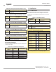
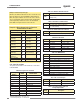
AO1 PEAK and AO2 PEAK Measurements
The AO1 PEAK and AO2 PEAK measurements store the
minimum/maximum values of Analog Output 1 and Analog
Output 2 respectively. When the EZ-ARRAY’s Analog Outputs
are configured to have Peak Detect = Enabled and Peak
Detect Reset = External Communications, then reading these
measurements will reset the Analog Output Peak Detect value.
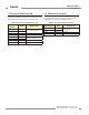
To enable this mode of operation, the Analog Output’s Config
Flags register (address 40026 – AO1, address 40030 – AO2)
must be configured as shown in Example A–7.