
Instruction Manual


P/N 130426 Rev. C 39
Banner Engineering Corp. •Minneapolis, U.S.A.
www.bannerengineering.com•Tel:763.544.3164
A-GAGE EZ-ARRAY
Instruction Manual
Appendix
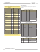
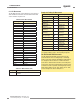
Table A–19. Cache Mode
Value Type Description
0 Standard Active measurements are cached
1 Extended Active measurements and channel states
are cached (decreases MAX scan rate)
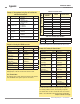
Analog Output 1 Configuration
The Analog Output 1 Configuration contains the settings for the
first analog output.
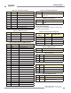
Table A–20. Analog Output 1 Conguration
Holding Register
Address
MASK Member Name
40026 LOW BYTE Config Flags
40026 HIGH BYTE RESERVED
40027 LOW BYTE Filter Speed
40027 HIGH BYTE RESERVED
40028 NULL Output
40028 SPAN Output
Table A–21. Cong Flags (Analog Outputs 1 and 2)
Bit Flag Description
0 Slope 0 = Negative, 1 = Positive
1 Measurement 0 = Measurement 2, 1 = Measurement 1
2 ZERO Value 00 = Hold, 01 = Minimum, 10 = Maximum
3
4 Peak Detect 0 = Disabled, 1 = Enabled
5 Peak Detect
Direction
0 = Maximum, 1 = Minimum
6 Status 0 = Disabled, 1 = Enabled
7 Peak Detect
Reset
0 = Auto, 1 = External Communications
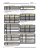
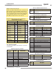
Table A–22. Filter Speed (Analog Outputs 1 and 2)
Value Filter Speed Description
0 Fast No filtering
1 Medium
Filter step response is 6 scans for
98% of signal
3 Slow
Filter step response is 24 scans for
98% of signal
Table A–23. NULL Output (Analog Outputs 1 and 2)
Range Description
0-4095
Minimum DAC value of Analog Output
(MUST be < SPAN Output)
Table A–24. SPAN Output (Analog Outputs 1 and 2)
Range Description
0-4095
Maximum DAC value of Analog Output
(MUST be > NULL Output)
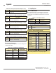
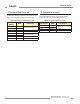
Analog Output 2 Configuration
The Analog Output 2 Configuration contains the settings for the
second analog output.
Table A–25. Analog Output 2 Conguration
Holding Register
Address
MASK Member Name
40030 LOW BYTE Config Flags
40030 HIGH BYTE RESERVED
40031 LOW BYTE Filter Speed
40031 HIGH BYTE RESERVED
40032
NULL Output
40033
SPAN Output
Discrete Output 1 Configuration
The Discrete Output 1 Configuration contains the settings for the
first discrete output.
Table A–26. Discrete Output 1 Conguration
Holding Register
Address
MASK Member Name
40034 LOW BYTE Config Flags
40034 HIGH BYTE RESERVED
40035
Scan Response
40036
Hysteresis LOW
40037
Hysteresis HIGH
40038
Threshold LOW
40039
Threshold HIGH
Table A–27. Cong Flags (Discrete Outputs 1 and 2)
Bit Flag Description
0 Status 0 = Disabled, 1 = Enabled
1 Type
0 = Measurement, 1 = Alarm/Health
(Discrete Output 1 can ONLY be of
type Measurement)
2 Polarity 0 = PNP, 1 = NPN
3 Mode*
0 = Normally Closed (Health)
1 = Normally Open (Alarm)
4 Measurement
0 = Measurement 2
1 = Measurement 1
*For Alarm/Health Type, Mode setting corresponds to 0=Health, 1=Alarm