
Instruction Manual

P/N 130426 Rev. C 37
Banner Engineering Corp. •Minneapolis, U.S.A.
www.bannerengineering.com•Tel:763.544.3164
A-GAGE EZ-ARRAY
Instruction Manual
Appendix
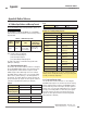
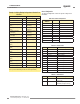
Example A–4. Writing Blanking Conguration to Blank the First
2 Channels
Request Response
Field Name (Hex) Field Name (Hex)
Slave Address 41 Slave Address 41
Function 10 Function 10
Starting Address (HIGH
Byte)
9C Starting Address
(HIGH Byte)
9C
Starting Address (LOW
Byte)
43 Starting Address
(LOW Byte)
43
Quantity of Registers
(HIGH Byte)
00 Quantity of Registers
(HIGH Byte)
00
Quantity of Registers
(LOW Byte)
17 Quantity of Registers
(LOW Byte)
17
Quantity of Bytes 2E CRC (LOW Byte) 51
Register 40003 (HIGH
Byte)
00 CRC (HIGH Byte) 43
Register 40003 (LOW
Byte)
03
Register 40004 (HIGH
Byte)
00
Register 40004 (LOW
Byte)
00
… …
… …
Register 40025 (HIGH
Byte)
00
Register 40025(LOW
Byte)
00
CRC (LOW Byte) 3A
CRC (HIGH Byte) 96
To Blank the first 2 channels, the Blanking 1-16 register (address
40003) is set to the two-byte value of 0x0003 (3 decimal).
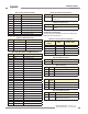
General Configuration
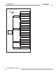
The General Configuration contains the general settings for the
EZ-ARRAY.
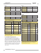
Table A–6. General Conguration
Holding Register
Address
MASK Member Name
40046 LOW BYTE Emitter Power
40046 HIGH BYTE Gain Method
40047 LOW BYTE Low Contrast Sensitivity
40047 HIGH BYTE HW Interface Flags
40048 LOW BYTE Measurement 1
40048 HIGH BYTE Measurement 2
40049 RESERVED
40050 Number of Dirty Channels
40051 Time of Service
40052
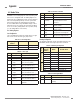
Table A–7. Emitter Power
Value Function Description
0 Disabled Disabled
1 Level 1 Power Setting 1 (Lowest)
2 Level 2 Power Setting 2
3 Level 3 Power Setting 3
4 Level 4 Power Setting 4
5 Level 5 Power Setting 5
6 Level 6 Power Setting 6
7 Level 7 Power Setting 7
8 Level 8 Power Setting 8
9 Level 9 Power Setting 9
10 Level 10 Power Setting 10
11 Level 11 Power Setting 11 (Highest)
Table A–8. Gain Method
Value Status Description
1 High-Excess Gain Fixed thresholds for maximum
excess gain
2 Low Contrast Adjustable percentage-based
thresholds (Straight Scan only)