
Instruction Manual

36 P/N 130426 Rev. C
Banner Engineering Corp. •Minneapolis, U.S.A.
www.bannerengineering.com•Tel:763.544.3164
A-GAGE EZ-ARRAY
Instruction Manual
Appendix
A.2 Modbus Tables
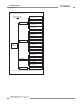
EZ-ARRAY uses the Holding Registers table for providing read-
write access to configuration data. The Holding Registers are
defined in the 40000-49999 address range. The Input Registers
table is used for providing read-only access to system status
and measurement data. The Input Registers are defined in
the 30000-39999 address range. EZ-ARRAY employs a direct
addressing scheme. For example, the input register at address
30000 is accessed by reading address 30000 (0x7530) directly
(i.e., the starting address is not an offset).
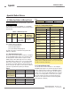
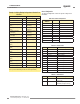
A.2.1 Holding Registers
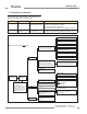
Scan Configuration
The Scan Configuration contains the settings for the scan type
and receiver’s remote teach wire (gray wire) function.
Table A–1. Scan Conguration
Holding Register
Address
MASK Member Name
40000 LOW BYTE Scan Type
40000 HIGH BYTE Remote Teach/Gate
Table A–2. Scan Type
Value Type Description
0 Disabled Scanning is Disabled
1 Straight Straight Scanning
2 Single Edge Scanning for Single Edge
3 Double Edge
– Step 1
Scanning for Edges of up to 3
objects (fires every channel)
4 Double Edge
– Step 2
Scanning for Edges of up to 3
objects (fires channels 1,3,5,…)
5 Double Edge
– Step 4
Scanning for Edges of up to 3
objects (fires channels 1,5,9,…)
6 Double Edge
– Step 8
Scanning for Edges of up to 3
objects (fires channels 1,9,17,…)
7 Double Edge
– Step 16
Scanning for Edges of up to 3
objects (fires channels 1,17,33,…)
8 Double Edge
– Step 32
Scanning for Edges of up to 3
objects (fires channels 1,33,65,…)
10 Carpet Nap Scanning for Carpet Nap Detection
Applications
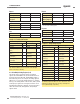
Table A–3. Remote Teach/Gate
Value Function Description
0 Disabled Disabled
1 Remote Teach Enabled with All Functionality
2 Alignment/
Sensitivity
Only Alignment, Blanking, &
Sensitivity Adjustments can be
performed
3 Gate – Active
High
Setting the gray wire in the high state
enables scanning
4 Gate – Active
Low
Setting the gray wire in the low state
enables scanning
5 Gate – Rising
Edge
A single scan will occur after the gray
wire goes from a low-to-high state
6 Gate – Falling
Edge
A single scan will occur after the gray
wire goes from a high-to-low state
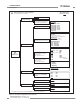
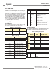
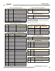
Blanking Configuration
The blanking configuration contains the blanking bit-mask for the
EZ-ARRAY channels. Each register represents 16 channels.
Table A–4. Blanking Conguration
Model
Holding
Register
Address
MASK Member Name
150–1800 mm
40003 LOW BYTE Blanking 1–8
40003 HIGH BYTE Blanking 9–16
… … …
40025 LOW BYTE Blanking 353–360
40025 HIGH BYTE (Pad byte)
2100–2400 mm
40250 LOW BYTE Blanking 1–8
40250 HIGH BYTE Blanking 9–16
… … …
40279 LOW BYTE Blanking 349–464
40279 HIGH BYTE Blanking 465–480
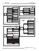
Table A–5. Blanking Bit-Mask
Value Status Description
0 Non-Blanked The channel will be used during scanning
1 Blanked The channel will be skipped during
scanning