
Instruction Manual


Banner Engineering Corp. •Minneapolis, U.S.A.
www.bannerengineering.com•Tel:763.544.3164
A-GAGE EZ-ARRAY
Instruction Manual
Table of Contents
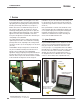
1. Overview ........................................ 1
1.1 System Components ..............................1
1.2 Features ........................................2
1.3 Configuration via DIP Switch or PC Interface ...........2
1.4 Status Indicators..................................3
1.5 Receiver Gray (Remote Teach) Wire ..................4
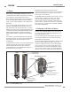
1.6 Scanning Method .................................5
1.7 Gain Configuration ................................7
1.8 Electronic Alignment Routine ........................8
1.9 Blanking ........................................8
1.10 Measurement Mode Selection . . . . . . . . . . . . . . . . . . . . . . 8
1.11 Analog Output Configuration .......................9
1.12 Discrete Output Configuration ......................9
1.13 Serial Communication ............................9
2. Components and Specifications .................... 10
2.1 Sensor Models ..................................10
2.2 Cordsets and Connections......................... 11
2.3 Alignment Aids .................................. 11
2.4 Accessory Mounting Brackets and Stands.............12
2.5 Replacement Parts...............................12
2.6 Specifications ...................................12
2.6 Specifications, continued ..........................13
2.7 Emitter and Receiver Dimensions ...................14
2.8 Standard Bracket Dimensions ......................15
3. Installation and Alignment ......................... 16
3.1 Mounting the Emitter and Receiver ..................16
3.2 Mechanical Alignment ............................17
3.3 Hookups .......................................18
3.4 Optical Alignment ...............................19
4. Using the Receiver User Interface................... 20
4.1 Configuration DIP Switch ..........................20
4.2 Alignment / Blanking Button (Electronic Alignment).......21
4.3 Gain (Sensitivity Adjust) Button .....................21
4.4 Inverting the 3-Digit Display ........................22
4.5 Troubleshooting and Error Codes ...................22
5. Using the PC Interface (Banner Sensors GUI)......... 23
5.1 Supplied Software ...............................23
5.2 Communications Connections ......................23
5.3 Accessing the GUI ...............................23
5.4 Factory Defaults .................................25
5.5 Alignment and Blanking ...........................25
5.6 Configuration Setup
...............................26
5.7 System Config View ..............................27
5.8 Analog Output Config View ........................28
5.9 Discrete Output Config View .......................28
5.10 Comm Config View..............................29
5.11 Part Number and Version Info View .................29
5.12 System Diagnostics View.........................29
5.13 Communications Troubleshooting ..................30
Appendix A. Modbus Reference ....................... 34
Glossary ....................................... 45