
Instruction Manual

P/N 130426 Rev. C 17
Banner Engineering Corp. •Minneapolis, U.S.A.
www.bannerengineering.com•Tel:763.544.3164
A-GAGE EZ-ARRAY
Instruction Manual
Installation
3.2 Mechanical Alignment
Mount the emitter and receiver in their brackets and position the
windows of the two units directly facing each other. Measure
from one or more reference planes (e.g., the building floor) to
the same point(s) on the emitter and receiver to verify their
mechanical alignment. Use a carpenter’s level, a plumb bob,
or the optional LAT-1-SS Laser Alignment Tool, or check the
diagonal distances between the sensors, to achieve mechanical
alignment.
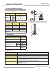
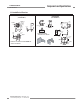
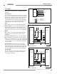
When alignment is difficult, a LAT-1-SS tool is useful to assist
or confirm alignment by providing a visible red dot along the
sensor’s optical axis (see Figure 3-3). Snap the LAT-1 clip onto
the sensor housing, turn on its laser emitter, and use a strip of
retroreflective tape at the opposite sensor to see the dot.
Also check “by eye” for line-of-sight alignment. Make any
necessary final mechanical adjustments, and hand-tighten the
bracket hardware. See Sections 3.4 and 4.2 for further alignment
information.
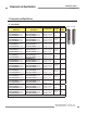
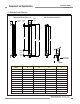
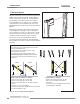
Figure 3-2. Sensor mounting, mechanical alignment
Angled or Horizontal Installations – verify that:
•DistanceXattheemitterandreceiverareequal.
•DistanceYattheemitterandreceiverareequal.
•DistanceZattheemitterandreceiverareequalfromparallel
surfaces.
•Verticalface(i.e.,thelens)islevel/plumb.
•Sensingareaissquare.Checkdiagonalmeasurementsifpossible;
see Vertical Installations, at right.
Vertical Installations – verify that:
•DistanceXattheemitterandreceiverareequal.
•Bothsensorsarelevel/plumb(checkboththe
side and face).
•Sensingareaissquare.Verifydiagonalmeasurementsif
possible (Diagonal A = Diagonal B).
Level Surface
Level Surface
XX
AB
Emitter Receiver
level level
level
level
Y Y
Z
Z
XX
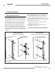
Verify that:
•Theemitterandreceiveraredirectlyoppositeeachother,and
nothing is interrupting the beams.
•Thesensingareaisthesamedistancefromacommon
reference plane for each sensor.
•Theemitterandreceiverareinthesameplaneandare
level/plumb and square to each other (vertical, horizontal,
or inclined at the same angle, and not tilted front-to-back or
side-to-side).
Figure 3-3. Optical alignment using the LAT-1-SS