A-GAGE EZ-ARRAY™ Instruction Manual ® Two-piece sensing array with 2 analog and 2 discrete outputs, plus serial output Features • A cost-effective, two-piece measuring light curtain designed for quick and simple installations with the sophistication to handle the toughest sensing applications • E xcels at high-speed, precise process monitoring and inspection, profiling, and web-guiding applications • A comprehensive combination of scanning options: – 14 measurement (“scan analysis”) modes – 3 scanning
Table of Contents A-GAGE EZ-ARRAY Instruction Manual 1. Overview . . . . . . . . . . . . . . . . . . . . . . . . . . . . . . . . . . . . . . . . . 1 1.1 System Components . . . . . . . . . . . . . . . . . . . . . . . . . . . . . . . 1 1.2 Features . . . . . . . . . . . . . . . . . . . . . . . . . . . . . . . . . . . . . . . . 2 1.3 Configuration via DIP Switch or PC Interface . . . . . . . . . . . . 2 1.4 Status Indicators . . . . . . . . . . . . . . . . . . . . . . . . . . . . . . . . . . 3 1.
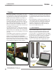
A-GAGE EZ-ARRAY Overview Instruction Manual 1. Overview The A-GAGE™ EZ-ARRAY™ measuring light screen is ideal for such applications as on-the-fly product sizing and profiling, edge-guiding and center-guiding, loop tensioning control, hole detection, parts counting, and similar uses (see Figure 1-1). Installation is easy, too. The emitter and receiver housings can be side-mounted or end-cap-mounted using the included endcap brackets; longer models also include a center bracket (see Section 3.1).
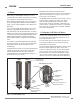
A-GAGE EZ-ARRAY Overview Instruction Manual Configurable beam blanking accommodates machine components and fixtures that must remain in or move through the light screen. Blanking may be set using the receiver interface, the teach wire, or the PC interface. 1.2 Features Built-in features in the EZ-ARRAY contribute to its ease of use. Many features are available using either the user-friendly receiver interface or the more advanced PC interface.
A-GAGE EZ-ARRAY Overview Instruction Manual sensors and a PC is accomplished via the serial output and Modbus RTU-485 interface. The software also provides alignment and diagnostics routines. An Alignment screen displays the individual status of each beam in the light screen, as well as the total number of beams, and totals of beams blocked, made, and blanked. Built-in diagnostics can be used to assess emitter and receiver status.
A-GAGE EZ-ARRAY Overview Instruction Manual Receiver Interface Status Indicators 1.5 Receiver Gray (Remote Teach) Wire The receiver has three status indicators: green/red System Status, yellow Modbus Activity, and red Modbus Error. The following table lists the indicator states. The receiver gray (remote teach) wire is used to electronically emulate the receiver push button functions (see Section 4.
A-GAGE EZ-ARRAY Overview Instruction Manual When the gray wire is disabled, the receiver is in continuous scan mode; it begins a new scan immediately after updating the outputs from the previous scan. (Continuous scan is used in most analog output applications and whenever continuous updating of the outputs is acceptable.) The gray wire is always enabled when in DIP switch mode. •R emote Teach — The gray wire provides the full Remote Teach functionality shown in Figure 1.5.
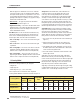
A-GAGE EZ-ARRAY Overview Instruction Manual Double-Edge Scan is used to detect two edges of a single object, for example, to determine box width measurements. Double-edge scan requires the selection of a step size: 1, 2, 4, 8, 16 or 32 beams. The sensor uses the steps to “skip” over beams, as follows: 1. The sensor activates beam 1 (closest to the sensor display end). 2. The sensor activates the next beam, determined by the step size.
A-GAGE EZ-ARRAY Overview Instruction Manual Array Length Straight Scan Maximum Scan Times (in milliseconds) Double-Edge Scan Single-Edge Step Step Step Step Scan 1 Beam 2 Beams 4 Beams 8 Beams Step 16 Beams Step 32 Beams 150 mm (5.9") 2.8 1.5 3.4 2.8 2.5 2.4 1.9 N/A 300 mm (11.8") 5.0 1.5 5.9 4.1 3.2 2.8 2.3 2.1 450 mm (17.7") 7.1 1.6 8.5 5.5 4.2 4.0 3.2 2.5 600 mm (23.6") 9.3 1.6 11.0 6.8 4.9 4.2 4.0 2.8 750 mm (29.5") 11.4 1.7 13.5 8.1 5.7 4.6 4.5 4.
A-GAGE EZ-ARRAY Overview 1.8 Electronic Alignment Routine The objective of the optical alignment process is to adjust the emitter light level to maximize sensor performance. Perform the alignment procedure at installation and again whenever the emitter and/or receiver is moved. During the alignment procedure, the receiver polls each beam channel to measure excess gain and performs a gain adjustment for each beam.
A-GAGE EZ-ARRAY Overview Instruction Manual • Transitions (TRN): The number of changes from blocked to clear status and from clear to blocked status. (If beams 6-34 are blocked, then there is a clear-to-blocked transition from beam 5 to beam 6, and a blocked-to-clear transition from beam 34 to beam 35.) Transition mode can be used to count objects within the array. • Outside Dimension (OD): The inclusive distance (measured in beams) from the first blocked beam to the last blocked beam.
Components and Specifications A-GAGE EZ-ARRAY Instruction Manual 2. Components and Specifications 2.1 Sensor Models Emitter/Receiver Model NPN Outputs Emitter/Receiver Model PNP Outputs Analog Output Array Length Y* Total Beams EA5E150Q Emitter EA5R150NIXMODQ Receiver EA5R150NUXMODQ Receiver EA5E150Q Emitter EA5R150PIXMODQ Receiver EA5R150PUXMODQ Receiver – Current (4–20 mA) Voltage (0–10V) 150 mm (5.
A-GAGE EZ-ARRAY Components and Specifications Instruction Manual 2.2 Cordsets and Connections Quick-Disconnect Sensor Cordsets Model Description MAQDC-815 Pinout 5 m (15') long Straight female connector, 8-pin Euro-style MAQDC-830 Ø15.0 mm (0.59") 9 m (30') long MAQDC-850 Female Connector Shown M12X1 Yellow White Gray Blue Pink 48.5 mm (1.91") 15 m (50') long Green Brown Red Communication Connections Model Description Pinout Communications Cables MQDMC-506 2 m (6.
Components and Specifications A-GAGE EZ-ARRAY Instruction Manual 2.4 Accessory Mounting Brackets and Stands See Section 2.5 for standard brackets. Order one EZA-MBK-20 bracket per sensor, two per pair. Model 50.0 mm (1.97") 44.4 mm (1.75") Description 20 mm (0.79") 4.2 mm (0.17") Universal adaptor bracket pair for mounting to engineered / slotted aluminum framing (e.g., 80/20™, Unistrut™). EZA-MBK-20 EZA-MBK-20 CL 39.2 mm (1.54") 58.2 mm (2.
A-GAGE EZ-ARRAY Components and Specifications Instruction Manual 2.
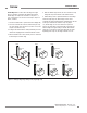
Components and Specifications A-GAGE EZ-ARRAY Instruction Manual 2.7 Emitter and Receiver Dimensions With mounting bracket flanges “out” 45.2 mm (1.78") 12 mm (0.47") With mounting bracket flanges “in” 36.0 mm (1.42") Y L1 L2 L3 56.0 mm (2.20") 4.2 mm (0.17") R13 mm (0.5") minimum bend 65 mm (2.6") Emitter or Receiver Model † Housing Length L1 Distance Between Bracket Holes L2 L3 Defined Area† Y EA5..150.. 227 mm (8.9") 260 mm (10.2") 199 mm (7.8") 150 mm (5.9") EA5..300.. 379 mm (14.
A-GAGE EZ-ARRAY Components and Specifications Instruction Manual 2.8 Standard Bracket Dimensions End Cap Brackets Center Bracket (model EZA-MBK-11*) (model EZA-MBK-12**) 4 x 5.8 mm (0.23") wide slots Ø 21.5 mm (0.85") Ø 33 mm (1.30") 4 x R 19.4 mm (0.76") 4 x 45 38.2 mm (1.50") 20 mm (0.79") 55 mm (2.17") 4.2 mm (0.17") 2 x 15 mm (0.59") Ø 60 mm 20 mm (0.79") 20 mm (0.79") 17.5 mm (0.69") 50 mm (1.97") 25 mm (0.98") 50 mm (1.96") 2 x 5 mm (0.20") 63.2 mm (2.49") 2 x 7 mm (0.
A-GAGE EZ-ARRAY Installation Instruction Manual 3. Installation and Alignment 3.1 Mounting the Emitter and Receiver Compact EZ-ARRAY emitters and receivers are easy to handle during mounting. When mounted to the sensor end caps, the supplied mounting brackets allow ±30° rotation. An emitter may be separated from 400 mm to 4 m (16" to 13') from its receiver.
A-GAGE EZ-ARRAY Installation Instruction Manual 3.2 Mechanical Alignment Mount the emitter and receiver in their brackets and position the windows of the two units directly facing each other. Measure from one or more reference planes (e.g., the building floor) to the same point(s) on the emitter and receiver to verify their mechanical alignment.
A-GAGE EZ-ARRAY Installation Instruction Manual 3.3 Hookups Refer to Figures 3-4, 3-5, and 3-6 for the appropriate hookup information. Modbus white D1/B/+ black D0/A/– blue common Serial Connection brown This connection is used only when the PC interface is also used. The receiver has a Modbus RTU-485 serial interface.
A-GAGE EZ-ARRAY Installation Instruction Manual 3.4 Optical Alignment a) After the electrical connections are made, power up the emitter and receiver. Verify that input power is present to both emitter and receiver; the emitter Status indicator and the receiver Status LED should be ON green. If the receiver Status LED is on red (and a “c” appears on the 3-digit display), refer to Section 4.5. NOTE: At power-up, all Zone indicators are tested (flash red), then the number of blocked beams is displayed.
Receiver Interface A-GAGE EZ-ARRAY Instruction Manual 4. Using the Receiver User Interface The receiver user interface comprises the six-position DIP switch, two push buttons, 3-digit display, and other indicators present on the receiver (see Section 1.4 for more complete status indicator information).
A-GAGE EZ-ARRAY Instruction Manual Because single-edge scan is capable only of measuring the height of an opaque object that blocks the bottom channel and all channels up to the height of the object, the pertinent measurement modes are LBB (last beam blocked) or TBB (total beams blocked). When single-edge scan is selected, the selected measurement mode will be applied to both analog outputs. Selection of OD/ID with single-edge scan will result in an error code.
Receiver Interface A-GAGE EZ-ARRAY Instruction Manual 4.5 Troubleshooting and Error Codes 4.4 Inverting the 3-Digit Display For instances where the sensors must be mounted in an inverted position, the 3-digit display can be can be inverted for readability. See the remote teach procedure (Section 1.5). The 3‑digit display can then be switched back to “normal” by repeating the procedure. NOTE: The periods on the three seven-segment indicators do not move when the display is inverted.
PC Interface A-GAGE EZ-ARRAY Instruction Manual 5. Using the PC Interface (Banner Sensors GUI) The full functionality of the EZ-ARRAY is available by making use of the PC interface (the graphic user interface, or “Banner Sensors GUI”). Refer to Section 1 for a full description of the available sensing modes and other features.
PC Interface A-GAGE EZ-ARRAY Instruction Manual Setup Select Sensor > Setup (Ctrl + S) to modify or view the configuration of the connected sensor pair. Refer to Figure 5-12 for an overview of available configuration options and Sections 5.6–5.13 for more information. Figure 5-5. Sensor menu, System Config view Figure 5-3. Sensor menu, Alignment/Status screen Connect / Disconnect To disconnect from a pair of sensors, select Disconnect (Ctrl + N) from the Sensor menu.
PC Interface A-GAGE EZ-ARRAY Instruction Manual 5.4 Factory Defaults Select Basic for an abbreviated list; select Advanced to access all communications fields Factory default selections in this section are designated with an underline. To reconfigure a sensor to the factory default optons, access the .xml default file from the folder Banner Engineering > Banner Sensors GUI > Configs > Defaults (see Section 5.1).
PC Interface The electronic alignment routine adjusts the emitted light level to maximize sensor perfomance. When the system exits alignment, the sensor records and stores channel signal strength and blanking information in non-volatile memory until electronic alignment is performed again. Perform the procedure at installation and again whenever the emitter and/or receiver is moved. (For Receiver interface software alignment instructions, see Section 4.2.
PC Interface A-GAGE EZ-ARRAY Instruction Manual Configuration Type determines whether the Receiver interface or the PC interface will control the sensing parameters. • DIP Switch: Receiver interface is in control. • Advanced: PC interface is in control. Select Advanced to override the receiver DIP switch settings and access configuration settings. (Settings can not be changed unless Advanced is selected.) Scan Configuration Figure 5-9.
PC Interface A-GAGE EZ-ARRAY Instruction Manual User Interface Options The user interface options control the Receiver user interface display and push buttons. • Display Orientation (Normal or Inverted) is used to invert the display to right-reading when sensors are mounted “upside down.” Note that the periods on the three seven-segment indicators do not move when the display is inverted. • Sensitivity Button field (Enabled or Disabled) is used to enable or disable the Sensitivity button for security.
PC Interface A-GAGE EZ-ARRAY Instruction Manual Health: Output is normally active, becomes inactive when an error occurs. Alarm: Output is normally inactive, becomes active when an error occurs. • Demodulation is used to smooth the discrete output response. Each discrete output can respond after each sensor scan, or the response time can be increased by increasing the demodulation.
PC Interface A-GAGE EZ-ARRAY Instruction Manual 5.13 Communications Troubleshooting The two most common communication errors are listed in the table below. For other errors, contact the factory. Description Corrective Action 6101 Error Code Modbus Timeout Error Message Timeout reached while communicating with sensor 1. Check sensor power. 2. Check communication cable connections. 3. Check Communication Settings in GUI. 4. Use Advanced Communication Settings to ping/discover sensor.
PC Interface A-GAGE EZ-ARRAY Instruction Manual A Sensor > Setup (Ctrl + S) > System Config View* NOTE: Underlined options designate default settings.
PC Interface B A-GAGE EZ-ARRAY Instruction Manual Sensor > Setup (Ctrl + S) > Analog Output Config View* NOTE: Underlined options designate default settings.
PC Interface A-GAGE EZ-ARRAY Instruction Manual F Sensor > Setup (Ctrl + S) > System Diagnostics View* (Not available until Connect is performed) NOTE: Underlined options designate default settings.
A-GAGE EZ-ARRAY Appendix Instruction Manual Appendix A. Modbus Reference A.1 Modbus Specifications and Message Formats For the latest Modbus protocol and specifications, please visit http://www.modbus.org The EZ-ARRAY is compliant with Modbus v1.1a. EZ-ARRAY utilizes the RTU transmission Mode. The RTU message frame is depicted below. Table A–1.
A-GAGE EZ-ARRAY Appendix Instruction Manual Request Request Function Code 1 byte 0x04 Function Code 1 byte 0x10 Starting Address 2 bytes 0x0000 to 0xFFFF Starting Address 2 bytes 0x0000 to 0xFFFF Quantity of Input Registers 2 bytes 0x0001 to 0x007D Quantity of Holding Registers 2 bytes 0x0001 to 0x007B Byte Count 1 byte 2 X N* Response Function Code 1 byte 0x04 Byte Count 1 byte 2 X N* Input Registers N X 2 Bytes Register Value * “N” is the number of holding registers Respo
A-GAGE EZ-ARRAY Appendix Instruction Manual Table A–3. Remote Teach/Gate A.2 Modbus Tables Value Function Description 0 Disabled Disabled 1 Remote Teach Enabled with All Functionality 2 Alignment/ Sensitivity Only Alignment, Blanking, & Sensitivity Adjustments can be performed 3 Gate – Active High Setting the gray wire in the high state enables scanning 4 Gate – Active Low Setting the gray wire in the low state enables scanning A.2.
A-GAGE EZ-ARRAY Appendix Instruction Manual Example A–4.
A-GAGE EZ-ARRAY Appendix Instruction Manual Table A–12. Number of Dirty Channels Table A–9. Low-Contrast Sensitivity Range Blocked Threshold Set Description Value Function 0 10% 10% below aligned signal 1 15% 15% below aligned signal Number of channels that need to be dirty before indicator is lit 2 20% 20% below aligned signal 3 25% 25% below aligned signal Table A–13.
A-GAGE EZ-ARRAY Appendix Instruction Manual Table A–19. Cache Mode Value Type Table A–24. SPAN Output (Analog Outputs 1 and 2) Description 0 Standard Active measurements are cached 1 Extended Active measurements and channel states are cached (decreases MAX scan rate) Range 0-4095 Description Maximum DAC value of Analog Output (MUST be > NULL Output) Analog Output 2 Configuration Analog Output 1 Configuration The Analog Output 1 Configuration contains the settings for the first analog output.
A-GAGE EZ-ARRAY Appendix Instruction Manual Table A–28. Scan Response (Discrete Outputs 1 and 2) Range Description Number of consecutive measurements before changing state 1-250 Table A–29. Hysteresis LOW (Discrete Outputs 1 and 2) Range Table A–30. Hysteresis HIGH (Discrete Outputs 1 and 2) Range Description Upper hysteresis threshold for discrete output (MUST be > Threshold HIGH) 2-481 Table A–31.
A-GAGE EZ-ARRAY Appendix Instruction Manual A.3.2 ALL Measurements The ALL Measurements section contains the current values of all the available measurements. The ALL Measurements data can be read after every third scan. Table A–36.
A-GAGE EZ-ARRAY Appendix Instruction Manual 0 Slope 1 Measurement 2 3 4 5 ZERO Value Peak Detect Peak Detect Direction 6 Status 7 Peak Detect Reset Description 0 = Negative 1 = Positive 0 = Measurement 2 1 = Measurement 1 00 = Hold 01 = Minimum 10 = Maximum 0 = Disabled, 1 = Enabled 0 = Maximum 1 = Minimum 0 = Disabled 1 = Enabled 0 = Auto 1 = External Communications Value X* X 1 X 1 1 Slave Address Function Starting Address (HIGH Byte) Starting Address (LOW Byte) Quantity of Registers (HIGH
A-GAGE EZ-ARRAY Appendix Instruction Manual Table A–41. Number of Emitter Channels Example continued from previous page Otherwise, the Channel States data can be accessed after every third scan (default). To set the EZ-ARRAY in Extended Cache Mode, the register at address 41002 must be set to a value of 1. This is a configuration register (Communications Configuration), so this register only needs to be set once. To exit Extended Cache Mode, the register must be set to a value of 0. Example A–10.
A-GAGE EZ-ARRAY Appendix Instruction Manual A.5 Receiver and Emitter Version Info The Receiver and Emitter Version Info section contains the part numbers and versions of the receiver and emitter firmware. A.6 Communications Version Info The Communications Version Info section contains the part number and version of the communications firmware. Table A–48.
A-GAGE EZ-ARRAY Instruction Manual Appendix Glossary Blanked Beam: A beam that is “ignored” by the receiver, as a result of a blanking program being applied to it. Beams (or groups of beams) are blanked when a component or fixture will remain in or move through the light screen array; blanking the affected beams prevents the component or fixture from causing false outputs. Blocked Beam: A beam that is obstructed between the emitter and the receiver, and is not blanked.
Banner Engineering Corp Limited Warranty Banner Engineering Corp. warrants its products to be free from defects in material and workmanship for one year following the date of shipment. Banner Engineering Corp. will repair or replace, free of charge, any product of its manufacture which, at the time it is returned to the factory, is found to have been defective during the warranty period.