
Manual

Safety Extension Modules – EM-FD-7G Series with Delayed Output
page 6
Connection to the Machine to be Controlled
Some machines, such as those using dynamic motor braking, require power to be
provided during the braking action. EM-FD-7G Series Safety Extension Modules offer
delayed OFF time to accomplish this type of controlled stop. This is a Category 1
Stop, per EN418 and NFPA 79.
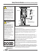
The hookup diagram in Figure 3 shows a generic connection of the four safety output
channels of the Safety Extension Module to Master Stop Control Elements MSC1
through MSC4. A Master Stop Control Element is defined as an electrically powered
device, external to the Extension Module, which stops the machinery being controlled
by immediately removing the electrical power to the machine and (when necessary)
by applying braking to dangerous motion (reference ANSI B11.19, section 5.2: “Stop
Control”).
To achieve control reliability, two redundant MSCs are required to
control each machine hazard.
To satisfy the requirements of control reliability, all MSCs must offer at least one
normally closed forced-guided monitor contact. One normally closed monitor contact
from each MSC is wired in series to the monitoring contact feedback input of the
Primary Safety Device, as shown in Figure 3. In operation, if one of the switching
contacts of any MSC fails in the shorted condition, the associated monitor contact will
remain open. As a result, it will not be possible to reset the Primary Safety Device.
NOTE: To allow the Primary Safety Device to properly monitor the MSC feedback
monitoring circuit, the installation’s total series resistance (wire and contact) must not
exceed manufacturer’s specifications (typically 30Ω resistance). If this value is
exceeded, the Primary Safety Device may not allow a reset of the System.
Many types of mechanisms are used to arrest dangerous machine motion. Examples
include mechanical braking systems, clutch mechanisms, and combinations of brakes
and clutches. Additionally, control of the arresting scheme may be hydraulic or
pneumatic. As a result, an MSC may be one of several control types, including a wide
variety of contactors and electromechanical valves. If your machine documentation
leaves any doubt about the proper connection points for the Safety Extension Module
output contacts, do not make any connections. Contact the machine builder for
clarification regarding connection to the MSCs.
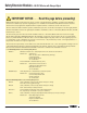
NOTICE regarding MSCs
To achieve control reliability, two
redundant Master Stop Control
Elements (MSCs) are required to
control each machine hazard. Each
MSC must be capable of immediately
stopping the dangerous machine
motion, irrespective of the state of
the other. Some machines offer only
one primary control element. For
such machines, it is necessary to
duplicate the circuit of the single
MSC to add a second MSC.
MSCs must offer at least one
forced-guided auxiliary contact
which is wired to the monitoring
contact feedback input of the
Primary Safety Device (see hookup
diagram, Figure 3).
WARNING . . .
MSC Monitoring
All Master Stop Control elements (MSCs), such as control relays, must be of forced-guided, captive contact design to
allow the MSC Monitoring circuit to detect unsafe failures within the master stop control elements. This monitoring
extends the safe switching point of the Primary Safety Device and the EM-FD-7G Series Safety Extension Module to the
MSC elements. For this monitoring to be effective, a minimum of two redundant MSCs are required to control each hazard. This is to
detect the unsafe failure of one MSC (e.g., a welded contact), while stopping the hazard and preventing a successive machine cycle
with the second MSC.
If the MSCs are the last electrically controlled device generating the hazard (i.e., not relays or contactors) and they do not have
forced-guided, captive contacts to monitor (such as a solenoid), then the customer must ensure that failure or fault of any single
component of the MSCs will prevent a successive machine cycle and will not result in a hazardous situation.
NOTE: MSC monitoring is also called external device monitoring (EDM), MPCE feedback, and relay backchecking.
!
WARNING . . .
Zero-
speed detection circuitry
is required for reverse
current braking applications
Applications which use reverse current
motor braking require zero-speed
detection circuitry to prevent the motor
from starting in the reverse direction.
This additional circuitry is necessary in
situations where motor reversal may
cause a machine hazard and/or
machine damage. Model EM-FD-7Gx
extension modules DO NOT provide
zero-speed detection circuitry.
!