
Instruction Manual

Safety Extension Module – Model EM-F-7G
page 6
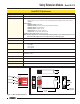
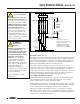
Connection to the Machine to be Controlled
The hookup diagram in Figure 3 shows a generic connection of the four safety output
channels of the Safety Extension Module to Master Stop Control Elements MSC1
through MSC4. A Master Stop Control Element is defined as an electrically powered
device, external to the Extension Module, which stops the machinery being controlled
by immediately removing the electrical power to the machine and (when necessary)
by applying braking to dangerous motion (reference ANSI B11.19, section 5.2: “Stop
Control”).
To achieve control reliability, two redundant MSCs are required to
control each machine hazard.
To satisfy the requirements of control reliability, all MSCs must offer at least one
normally closed forced-guided monitor contact. One normally closed monitor contact
from each MSC is wired in series to the monitoring contact feedback input of the
Primary Safety Device, as shown in Figure 3. In operation, if one of the switching
contacts of any MSC fails in the shorted condition, the associated monitor contact will
remain open. As a result, it will not be possible to reset the Primary Safety Device.
Many types of mechanisms are used to arrest dangerous machine motion. Examples
include mechanical braking systems, clutch mechanisms, and combinations of brakes
and clutches. Additionally, control of the arresting scheme may be hydraulic or
pneumatic. As a result, an MSC may be one of several control types, including a wide
variety of contactors and electromechanical valves. If your machine documentation
leaves any doubt about the proper connection points for the Safety Extension Module
output contacts, do not make any connections. Contact the machine builder for
clarification regarding connection to the MSCs.
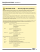
Initial Checkout Procedure
NOTE:
The Safety Extension Module can be used safely only when its operation is
controlled via an appropriate Primary Safety Device, connected to the
Extension Module according to the wiring diagram shown in Figure 3.
Checkout procedure:
1) Remove the power controlling (and switched by) the machine control elements
(see Caution at right).
2) Verify that the Primary Safety Device which will be controlling the Safety
Extension Module is operating correctly, according to its product documentation
and manufacturer’s recommendations.
3) Confirm proper connection of the Safety Extension Module to the controlling
Primary Safety Device according to the wiring diagram (see Figure 3).
4) Verify that all four Safety Extension Module output contacts follow exactly the
operation of the safety output contacts of the controlling Primary Safety Device,
when the Primary Safety Device is operated according to its product
documentation and manufacturer’s recommendations.
CAUTION . . .
Disconnect Power Prior
to Checkout
Before performing the initial
checkout procedure, make certain
all power is disconnected from the
machine to be controlled.
Dangerous voltages may be present
along the Safety Extension Module
wiring barriers whenever power to
the machine control elements is ON.
Exercise extreme caution whenever
machine control power is or may
be present.
NOTICE regarding MSCs
To achieve control reliability, two
redundant Master Stop Control
Elements (MSCs) are required to
control each machine hazard. Each
MSC must be capable of immediately
stopping the dangerous machine
motion, irrespective of the state of
the other. Some machines offer only
one primary control element. For
such machines, it is necessary to
duplicate the circuit of the single
MSC to add a second MSC.
MSCs must offer at least one
forced-guided auxiliary contact
which is wired to the monitoring
contact feedback input of the
Primary Safety Device (see hookup
diagram, Figure 3).