
Instruction Manual

page 5
Safety Extension Module – Model EM-F-7G
WARNING . . .
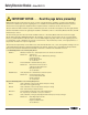
Use of Arc Suppressors
If arc suppressors are used, they
MUST be installed as shown across
the actuator coil of the master stop
control elements (MSC1 to MSC4).
NEVER install suppressors directly
across the output contacts of the
Safety Extension Module. It is
possible for suppressors to fail as a
short circuit. If installed directly
across the output contacts of the
Safety Extension Module, a short-
circuited suppressor will create an
unsafe condition which could result
in serious injury or death.
!
WARNING . . .
Maintain Control
Reliability
NEVER wire an intermediate device
(e.g., a programmable logic
controller/ PLC), other than a safety
relay, between any safety output of
the Safety Extension Module and the
master stop control element it
switches. To do so sacrifices the
control reliability of the control-to-
machine interface, and creates an
unsafe condition which could result in
serious injury or death. Whenever a
safety relay is added as an
intermediate switching device, a
normally-closed forced-guided monitor
contact of that relay must be added to
the series feedback loop.
(Reference ANSI B11.1 – 1988,
Appendix B4)
!
23 33 43
14 24 34 44
EM-F-7G
0
V dc
+24V ac/dc
L1
L2
13
A2
Machine Control Circuit
Primary
Safety
Device
Monitoring Contact
Feedback Input
Monitoring Contact
Feedback Input
A1 Y1
MSC1
MSC Monitor Contacts
MSC2 MSC3 MSC4
MSC1
*
MSC2
*
MSC3
*
MSC4
*
Machine
Master Stop
Control Elements
*Arc Suppressors
(See Warning)
Y2
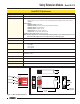
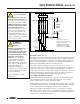
Figure 3. Generalized EM-F-7G hookup
NOTE:
This hookup is general in
nature. Your specific hookup
may vary significantly,
depending on the Primary
Safety Device used and the
machine control configuration.
One-Channel Control (Figure 3)
One-channel control affords simplicity of wiring. However, one-channel wiring requires
eliminating the possibility of an unsafe failure of the control wires (which connect the
output of the Primary Safety Device to the input of the Extension Module). One of the
ways to reduce the probability of such failure is to locate the Primary Safety Device
adjacent to the Safety Extension Module, in the same enclosure.
The output of the Primary Safety Device must consist of two or more series-
connected, normally open contacts, coming from forced-guided safety relays. These
contacts must be monitored for failure by the Primary Safety Device. In addition, a
single contact failure cannot prevent normal stopping action, and a successive cycle
cannot be initiated until the failure has been corrected. An example of this type of
output is any single output channel of a Banner E-stop safety module.
Use of Multiple Safety Extension Modules
Multiple Safety Extension Modules may be connected to one Primary Safety Device
which has additional unused output safety channels. However, only one Safety
Extension Module may be wired per output safety channel.
A Safety Extension Module may be controlled by an output safety channel of another
Safety Extension Module. However, the delay times of both Safety Extension Modules
must be added together to determine their combined output response time.
Whenever more than one Safety Extension Module is controlled by one Primary
Safety Device, the monitoring contacts of all Safety Extension Modules (terminals Y1
and Y2) must be wired together in series and connected to the Monitoring Contact
Feedback Input of the Primary Safety Device.