
Instruction Manual
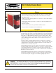

Safety Extension Module – Model EM-F-7G
page 4
Installation
Primary Safety Device Requirements
Model EM-F-7G Safety Extension Module is driven by one safety output channel of a
Primary Safety Device. The design of the Primary Safety Device must meet OSHA and
ANSI control reliability requirements. The EM-F-7G must be used only with a
Primary Safety Device which has a dedicated input for feedback monitor contacts
(see hookup diagram, Figure 3).
The output channel of the Primary Safety Device must meet the following
requirements:
• Include two (or more) redundant, normally open forced-guided (positive-guided)
contacts,
• Be self-monitored to result in a safe (open) condition in the event of a contact
failure, and
• Be capable of switching 40 to 100 mA at 13 to 27V ac/dc.
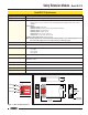
Mechanical Installation
The model EM-F-7G Safety Extension Module must be installed inside an enclosure. It is
not designed for exposed wiring. It is the user’s responsibility to house the Extension
Module in an enclosure with NEMA 3 (IEC IP54) rating, or better.
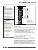
Dimensions of the Safety Extension Module are shown in Figure 2; it mounts directly to
standard 35mm DIN rail.
Electrical Installation
Because the Extension Module can be used with many different Primary Safety Devices
and can interface to a multitude of machine control configurations, it is not possible to
give exact wiring instructions for the output contacts. The following guidelines are general
in nature.
The output contacts of the Extension Module have no delay function. They typically will
open within 35 milliseconds after the controlling contacts coming from the Primary Safety
Device open.
CAUTION . . .
Dangerous Voltages
Always disconnect all power from
the Safety Extension Module, the
Primary Safety Device, and from
the machine being controlled
before making any wire
connections. Electrical installation
and wiring must be made by
qualified personnel and must
comply with the NEC (National
Electrical Code), EN 60204-1 and -2,
and all applicable local standards
and codes.
WARNING . . .
Not for
Use As a Stand-Alone
Safety Relay
1) DO NOT connect E-stop switches,
2-hand control switches, safety
interlock switches, or similar
devices directly to this Extension
Module.
2) ALWAYS connect terminals Y1
and Y2 of this Extension Module
to the monitoring input of the
Primary Safety Device that
controls it (see Figure 3).
This Safety Extension Module does
not have the circuitry required to
perform a self-check. A single fault
inside the unit or in external devices
like switches or E-stop buttons
connected to the unit can go
undetected and create an unsafe
condition. Failure to properly
connect this Safety Extension
Module to a control-reliable
Primary Safety Device could result
in serious injury or death.
!