
Instruction Manual

page 3
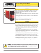
Safety Extension Module – Model EM-F-7G
Supply Protection Circuitry
Application Notes There are no adjustments and no user-serviceable parts. See page 6 for information regarding repair service.
Protected against transient voltages and reverse polarity
Output Configuration Four output channels:
Each channel is a series connection of two forced-guided (positive-guided) safety relay contacts –
AgSnO
2
Contact ratings:
Maximum voltage: 250V ac/dc
Maximum current: 6 A ac/dc (at specified operating temperature)
Minimum current: 30 mA @10V dc
Maximum power: 1500VA, 150 W
Mechanical life: 10,000,000 operations
Electrical life: 100,000 at full resistive load
Feedback contact rating (Y1-Y2): 250V ac/dc @ 3A
NOTE: Transient suppression is recommended when switching inductive loads. Install suppressors across
load. Never install suppressors across output contacts (see Warning, page 5).
Output Response Time 35 milliseconds typical
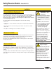
Status Indicators 3 green LED indicators:
Power ON
K1 energized
K2 energized
Input Requirements Input from Primary Safety Device must be capable of switching 40 to 100mA @ 13 to 27V ac/dc.
Construction Polycarbonate housing.
Mounting Mounts to standard 35 mm DIN-rail track.
Vibration Resistance 10 to 55Hz @ 0.35 mm displacement per IEC 68-2-6
Operating Temperature 0° to +50°C (+32° to 122°F)
Supply Voltage and Current A1-A2: 24V ac/dc, +/-10%, 10% maximum ripple on dc
Model EM-F-7G Specifications
Environmental Rating Rated NEMA 1, IEC IP20. Safety Extension Module must be installed inside an enclosure rated NEMA 3
(IEC IP54), or better.
13 23 33
14 24 34
13
Power
CH.
CH.
1
2
23 33 43
14 24 34 44
A1 Y1 Y2
43 44 A2
EM-F-7G
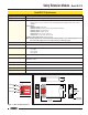
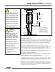
35.0 mm
(1.38")
DIN Mounting Slot
DIN Mounting
Tab (Supplied)
118.2 mm
(4.65")
22.5 mm
(0.88")
80 mm
(3.15")
82.0 mm
(3.23")
Figure 2. EM-F-7G Safety Extension Module enclosure dimensions
13 23 33
14 24 34
13
Power
CH.
CH.
1
2
23 33 43
14 24 34 44
A1 Y1 Y2
43 44 A2
EM-F-7G
K1 Energized
Input Power
ON
K2 Energized
Figure 1. EM-F-7G status indicators