
User Manual
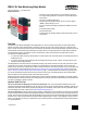

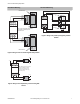

One-Channel Monitoring Two-Channel Monitoring
Mechanical stop
Guard #1
open
Guard #2
open
Blue
Gray
Black
Brown
SI-MAG..SM
SI-MAG..MM
SI-MAG..SM
SI-MAG..MM
Mechanical stop
Blue
Gray
Black
Brown
NOTE: If only one magnetic safety switch
is used, select 1-channel input and
jumper S23 to S21.
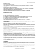
S12
S13
S11
S23
S22
S21
Figure 2. Wiring to two 4-wire coded magnetic safety switches
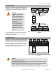
Guard
Mechanical
stop
Mechanical
stop
open
S12
S13
S11
S23
S22
S21
Guard #1
NOTE: Guard shown in closed position.
Figure 3. Wiring to two positive-opening safety interlock
switches
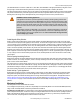
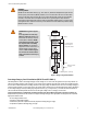
S12
S13
S23
S22
NOTE: If PNP current-sourcing signals
are used, the GM-FA-10J and the
current-sourcing devices must be
powered from the same DC supply
and Common (Com).
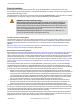
A1
A2
+24V dc
0V
+24V dc
+24V dc
N.O.
N.C.
N.O.
N.C.
0V
0V
Figure 4. Wiring to two complementary current-sourcing PNP
devices
GM-FA-10J Gate Monitoring Safety Module
P/N 060998 Rev. F www.bannerengineering.com - tel: 763-544-3164 7