
User Manual


E-Stop Safety Module – Model ES-FA-6G
page 10
Supply Protection Circuitry
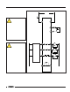
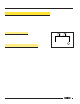
Dimensions See Figure 4.
Protected against transient voltages and reverse polarity
Output Configuration Outputs (K1 & K2): three redundant (total of six) safety relay (forced-guided) contacts – AgSnO
2
one auxiliary non-safety monitor output (open when both K1 and K2 are energized;
closed when either K1 or K2 are de-energized)
Contact ratings:
Maximum voltage: 250V ac or 250V dc
Maximum current: 6 A ac or dc
Minimum current: 30 mA @ 10V dc
Maximum power: 1500VA, 150W
Mechanical life: 10,000,000 operations
Electrical life: 100,000 at full resistive load
NOTE: Transient suppression is recommended when switching inductive loads. Install suppressors
across load. Never install suppressors across output contacts (see Warning, page 5).
Output Response Time 35 milliseconds typical
Status Indicators 3 green LED indicators:
Power ON
K1 energized
K2 energized
Input Requirements E-stop switch must have a normally closed contact capable of switching 40 to 100mA @ 13 to 27V ac/dc.
Reset switch must have one normally open contact capable of switching 20 to 30mA @ 13 to 27V ac/dc.
Housing Polycarbonate. Rated NEMA 1; IEC IP40, Terminals IP20
Mounting Mounts to standard 35 mm DIN rail track. Safety Module must be installed inside an enclosure rated NEMA 3
(IEC IP54), or better.
Vibration Resistance 10 to 55Hz @ 0.35mm displacement per IEC 68-2-6
Operating Conditions Temperature: 0° to +50°C (+32° to 122°F)
Maximum Relative Humidity: 90% @ +50°C (non-condensing)
Supply Voltage and Current 24V ac/dc, +/- 10%; 50/60Hz
Power consumption: approx. 2W/0.75VA
E-Stop Safety Module Product Specifications