
User Manual
Backdoor Timer
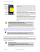
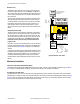
The Backdoor Timer allows the user to select a maximum period of
time when muting is allowed to occur (see Figure 5). The Backdoor
Timer helps to hinder the intentional defeat of the muting devices and
it is also useful in detecting common mode failures that could affect
the mute devices.
The timer begins when the second muting device makes the simulta-
neity requirement (actuated within 3 seconds of the first muting de-
vice being actuated), and will allow a mute to continue for the prede-
termined time. After the timer expires, the mute cycle will end – no
matter what the signal from the mute devices indicates – and the
safety outputs will open (even if the two-hand control switches are ac-
tuated).
Safety Stop Interface (SSI)
The SSI provides for easy integration of safeguards, E-stop buttons,
process control, etc. This input is always active: opening either chan-
nel will cause the AT-..M-11KM to issue a stop command. The chan-
nels operate concurrently (both must open and re-close, but not nec-
essarily within a certain time frame). If the SSI is not to be used,
terminal X3 must be jumpered to X4, and terminal X5 must be
jumpered to X6.
If the SSI is to be used, the connected device(s) must have electrical-
ly isolated, redundant hard contacts (voltage-free). See Figure 11 for
hookup information and Specifications on page 15 for contact spec-
ifications.
A variety of safety systems can be interfaced with the SSI. Each safe-
ty application has unique application requirements, and the user is re-
sponsible for ensuring proper installation, use, and compliance with
all relevant standards and regulations. If there are any questions,
contact the Banner Factory Applications Group to discuss your inten-
ded use.
Z1 Z2
M11 M12 M21 M22
S12
A1 A2 B1
B2
13 14 23 24
S11
S13
Z3 Z4 Y1 Y2
X3 X4 X5 X6 Y30 Y31 Y32 Y33
S21S22 S23
Powe r
Faul t
Input 1
Input 2
SSI
Mutin g
Output
K1
K2
K1
K2
31
32
A1 A2 B1 B2
Z3 Z4 Y1 Y2 M11 M12 M21 M22
S12 S11 S13
S22 S21 S23 GND Z1 Z2
X1 X2
31 32
13 14 23 24
X3 X4 X5 X6 Y30 Y31 Y32 Y33
DIP Switch
Bank "A"
S1.1
S1.2
S1.3
DIP Switch
Bank "B"
S2.1
S2.2
S2.3
Remove terminal blocks to
access configuration
DIP switches
ON/OFF
31 X1 X232
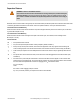
Configuration DIP Switches
Mute Lamp Output (ML) S1.3/S2.3
OFF = Monitored ML*
ON = Non-monitored ML
Backdoor Timer
S1.1/S2.1 S1.2/S2.2 Time
OFF OFF 30 seconds
OFF ON *60 seconds
ON OFF 300 seconds
ON ON Infinite
* Factory Default Setting
Figure 5. Backdoor Timer Setup
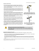
Mechanical Installation
Installation of the DUO-TOUCH SG Safety Module
The Module must be installed inside a NEMA 3 (IEC IP54) rated, or better, enclosure. It is not designed for exposed wiring. See Dimen-
sions on page 19 for Safety Module Dimensions. The device mounts directly onto a standard 35 mm DIN rail.
Heat Dissipation Considerations
For reliable operation, the user must ensure that the operating specifications are not exceeded. The enclosure must provide adequate
heat dissipation, so that the air closely surrounding the Module does not exceed the maximum operating temperature stated in the Speci-
fications on page 15 . Methods to reduce heat build-up include venting, forced airflow (e.g., exhaust fans), adequate enclosure exterior
surface area, and spacing between modules and other sources of heat.
DUO-TOUCH
® SG Two-Hand Control Modules
P/N 109782 Rev.B www.bannerengineering.com - tel: 763-544-3164 7