
User Manual
The connection of the safety outputs must be in such a
manner that the stop command issued by the AT-
xM-11KM can not be overridden by a device or circuit
that is not at the same level of safety integrity. This
means that the safety outputs are interfaced on the
output of the machine logic (e.g., PLC or PC). Then,
normally, a feedback signal identifies to the machine
logic the status of the safety module and, if possible,
the status of the MPCEs. If interposing relays are
used, they must be of mechanically linked (forced-gui-
ded) design and monitored by the MPCE Monitoring
Circuit (Y1/Y2).
As a summary, Control Reliability (OSHA
29CFR1910.217, ANSI B11, and ANSI/RIA R15.06)
and Category 3 and 4 (ISO13849-1) requirements de-
mand that a single failure does not lead to the loss of
the safety function, or does not prevent a normal or im-
mediate stop from occurring. The failure or the fault
must be detected at or before the next demand of
safety (e.g., at the beginning or end of a cycle, or when
a safeguard is actuated). The safety-related function of
the machine control then must issue an immediate
stop command or prevent the next machine cycle or
hazardous situation until the failure or fault is correc-
ted. The user must refer to the relevant standard(s)
for complete information.
X2
MPCE1 MPCE2
A2
Y1
(1)
Y2
+24V dc
+0V dc
24V dc
Connections to
actuation devices
Z1
A1
Z2
S12
S11
S13
S22
K1 K2
13
23
S21
S23
AT-GM-11KM
AT-HM-11KM
11 5V ac
230V ac
14
24
31 32
Y30
Y31
Y32
Y33
B2 0V dc for AC hookup
B1
*
*
MPCE
1
MPCE
2
Ma chi ne
Control
Circuit
(1) See warni ng at ri ght regardi ng
in termed iate swit ching devices
(Depending on mo del )
SSI1
SSI2
(2)
(2)
M1
M2
(2) Jumper SSI input s if not used
M1 1
M1 2
M2 1
M2 2
X3
X4
X5
X6
Feedback
(op tiona l)
Z3
Z4
X1
ML
Mu te
Lamp
ME
Mu te
Enabl e
+
NOTE:
See Figures for
alternate M1/M2
hookups
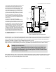
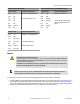
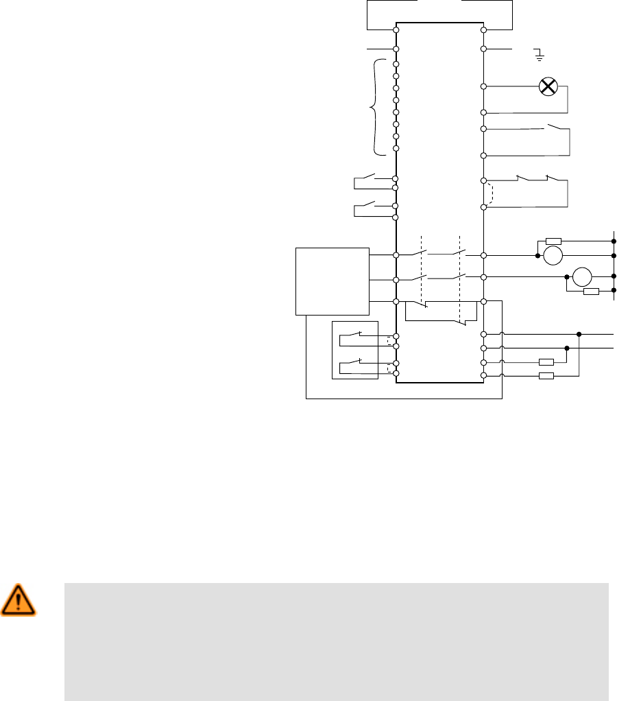
Figure 11. Machine control circuit connections
As shown in Figure 11, a normally-closed, mechanically linked monitor contact from each of the two MPCEs must be connected in series
across terminals Y1 and Y2. This allows the Safety Module to monitor the state of the MPCEs, and to prevent a successive machine
cycle, if an MPCE fault is detected. Monitoring MPCE contacts is one method of maintaining control reliability. When MPCE monitor
contacts are not available, a jumper wire must be installed across terminals Y1 and Y2.
When a jumper wire is used (dotted line between Y1 and Y2 in Figure 11), it is the user’s responsibility to provide an appropriate level of
safety for the means of machine interfacing to ensure that any single MPCE component failure will not result in the loss of safety.
WARNING: Use of Arc Suppressors
If arc suppressors are used, they MUST be installed as shown across the coils of the Machine Primary
Control Elements (MPCEs). NEVER install suppressors directly across the output contacts of the
Safety Module. It is possible for suppressors to fail as a short circuit. If installed directly across the
output contacts of the Safety Module, a short-circuited suppressor will create an unsafe condition
which could result in serious injury or death.
When switching inductive ac loads, it is good practice to protect the Safety Module outputs by installing appropriately-sized arc suppres-
sors. However, if arc suppressors are used, they must be installed across the load being switched (e. g., across the coils of external
safety relays), and never across the Safety Module’s output contacts.
DUO-TOUCH® SG Two-Hand Control Modules
12 www.bannerengineering.com - tel: 763-544-3164 P/N 109782 Rev.B