
User guide
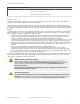
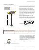
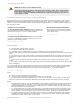
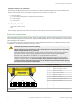
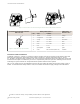
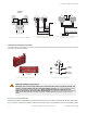
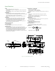

Figure 5. Use the slots in the run bar housing to hold the cover for the terminal connection
8-Pin Mini-Style Output QD Connector
Male Face View
Mating Cable: QDS-8..C SAE H1738-2
Alternate Color
1
Pin Color Function
1
2
3
8
7
6
5
4
Figure 6. 8-pin Mini-style QD Connection
1 brown +24 V dc orange
2 orange/black N.O. STB2 blue
3 orange N.C. STB2 white/black
4 white N.C. STB1 black
5 black N.O. STB1 white
6 blue 0 V dc red
7 green/yellow Gnd/PE green
8 violet Not Connected (future use) red/black
Connection of STB Touch Buttons
To maintain a Type IIIC / Category 4 connection, both the normally open and the normally closed outputs of each STB
button must be connected to a two-hand control system or module (e.g., Banner model AT-FM-10K, AT-..M-13A,
AT-..M-11KM or the Banner Safety Controller SC22-3) that meets the requirements listed in the Applications section and
monitors the STB outputs such that if they are not in a complementary state (one open/non-conducting and one closed/
conducting) the system will lock out and prevent further operation until the fault is repaired.
The +24 V dc supply power for the STB buttons must be the same supply that powers the two-hand control system or
module. If a DUO-TOUCH SG safety module is used, use terminals Z1 and Z2 for supply voltage for the STB buttons.
1
Listed as a customer courtesy. Verify suitability of these cables for each application.
DUO-TOUCH Run Bar with STB Buttons
Datasheet 131634_web Rev.
E
www.bannerengineering.com - tel: 763-544-3164 7