
Safety Interlock Switches Owner's manual

P/N50159Rev.F 7
Banner Engineering Corp. • Minneapolis, MN U.S.A
www.bannerengineering.com • Tel: 763.544.3164
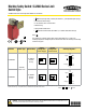
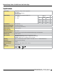
Machine Safety Switch: SI-LM40 Series Limit Switch Style
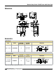
Dimensions
64.0 mm
(2.52")
18.0 mm
(0.71")
4.0 mm
(0.16")
35.0 mm
(1.38")
26.0 mm
(1.02")
35.0 mm
(1.38")
26.0 mm
(1.02")
25.0 mm
(0.98")
56.0 mm
(2.20")
10.0 mm
(0.39")
M4
18.0 mm
(0.71")
53.0 mm
(2.09")
56.5 mm
(2.22")
2.0 mm
(0.08")
40.0 mm
(1.57")
Ø5.2 mm
(Ø0.20")
77.5 mm
(3.05")
30.0 mm
(1.18")
M20x1.5
60.0 mm
(2.36")
17.5 mm
(0.69")
7.5 mm
(0.30")
16.0 mm
(0.63")
17.5 mm
(0.69")
42.0 mm
(1.65")
33.0 mm
(1.30")
M20x1.5
16.0 mm
(0.63")
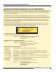
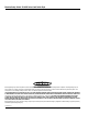
Accessories
Cable Glands
Size Model
Used with
Switch Models
For Cable
Diameters
Dimensions
M20x1.5Metal
SI-QM-CGM20
All
5.0to12.0mm
(0.20"to0.47")
M20 x 1.5
24.0 mm
(0.94")
35.5 mm
(1.40")
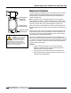
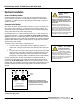
Replacement Parts
Description Model*
Used with
Switch Models
Thread
Conversion
Dimensions
½"-14NPTMetal
ConduitAdaptor
SI-QM-M20
All
M20x1.5to
½"-14NPT
23.0 mm
(0.91")
M20 x 1.5
24.0 mm
(0.94")
1/2"-14 NPT
Internal Thread
O-ring
*NOTE:Oneconduitadapterissuppliedwitheachswitch.