
Safety Interlock Switches Manual

Machine Safety Switch – SI-LM40 Series Limit Switch Style
P/N 49372 rev. D 3
Banner Engineering Corp. • Minneapolis, MN U.S.A.
www.bannerengineering.com • Tel: 763.544.3164
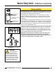
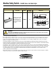
Figure 2. Actuator head may be rotated in
90º increments.
Mechanical Installation
The actuator head may be rotated, if desired, to any of four positions, in 90° increments.
To reposition the actuator head, unscrew the four mounting bolts, turn the head to the
desired position, and re-tighten the bolts (see Figure 2).
All mounting hardware is supplied by the user. The fasteners must be of sufficient
strength to guard against incidental breakage. Use of permanent fasteners or locking
hardware is recommended to prevent loosening or displacement of the actuator and
switch body.
The mounting holes in the switch body accept M5 (#10) screws. There are four holes on
a standard limit switch mounting pattern of 30 x 60 millimeters. The two mounting holes
on the actuator are spaced 20 millimeters apart. The grommet and sleeve design allows
a small amount of movement (i.e., misalignment) when the actuator engages the switch
body. The sleeves accept M4.5 (#8) screws.
Position the switch, with its actuator fully engaged, in the mounting location and mark the
mounting holes. Fasten the switch body and the actuator in place. The non-adjustable
(rigid) in-line actuators includes floating sleeves in the mounting holes to allow some
forgiveness for switch-to-actuator alignment. Take care to not over-tighten the actuator
fasteners so as to allow this movement. After the mounting hardware is secure, check
the actuator/switch engagement for misalignment and binding.
IMPORTANT: A safety switch must be installed in a manner which discourages
tampering or defeat. Mount switches to prevent bypassing of the switching
function at the terminal chamber. A switch and its actuator must never be used as
a mechanical stop. Overtravel may cause damage to switch.
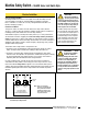
WARNING ...
It must not be possible for
personnel to reach any
hazard point through an opened guard (or
any opening) before hazardous machine
motion has completely stopped. Please
reference OSHA CFR 1910.217 and ANSI
B11 standards (see page 2) for information
on determining safety distances and safe
opening sizes for your guarding devices.
90º
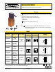
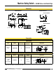
Round (5 mm) holes
for permanent
installation (2X)
Slotted holes for initial
alignment only (2X)
Remove to access wiring
chamber (2X)
Figure 1. Features
E