
Safety Interlock Switches Manual

Printed in USA 07/06 P/N 49372 rev. D
Machine Safety Switches
®
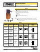
SI-LM40 Series Limit Switch Style with In-Line Actuator
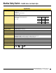
Kit Model
†
Actuator Type
†
Interlock Body
†
Contact
Configuration
(Actuator Engaged)
Contact
Configuration
(Actuator Removed)
Switching
Diagram
SI-LM40MKHD
SI-QM-SSA
Straight,
Rigid, In-Line
SI-LM40KHD
with
Metal Housing
SI-LM40MKHFD
SI-QM-SMFA
Right-angle,
Flexible, In-Line
SI-LM40MKHE
SI-QM-SSA
Straight,
Rigid, In-Line
SI-LM40KHE
with
Metal Housing
SI-LM40MKHFE
SI-QM-SMFA
Right-angle,
Flexible, In-Line
SI-LM40MKHF
SI-QM-SSA
Straight,
Rigid, In-Line
SI-LM40KHF
with
Metal Housing
SI-LM40MKHFF
SI-QM-SMFA
Right-angle,
Flexible, In-Line
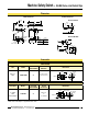
Contacts: Open Closed Transition
Models
† A kit contains an interlock and actuator. Individual interlock bodies or actuators are
for replacement purposes only. See page 7 and the Warning on page 8.
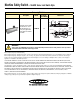
Features
• Positive opening safety contacts (IEC 60947-5-1) (not dependent upon springs)
• Standard limit switch metal housing (EN 50041)
• Choose either of two stainless steel actuator types:
- Rigid in-line
- Flexible in-line
•
Protective Earth Terminal (IEC 60947-1)
23 24
11 12
23 24
11 12
9 (0.35)
0 (0)
10 (0.39)
40 (1.58)
Engaged
Disengaged
11-12
23-24
Safety
Monitor
mm (in)
11 (0.43)
21 22
11 12
21 22
11 12
11 (0.43)
0 (0)
14 (0.55)
40 (1.58)
Engaged
Disengaged
11-12
21-22
Safety
Safety
mm (in)
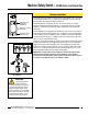
NOTE: This symbol for a positive-opening safety contact (IEC 60947-5-1) is used in the
switching diagrams to identify the point in actuator travel where the normally closed
safety contact is fully open.
25 26
15 16
33 34
25 26
15 16
33 34
10.5 (0.39)
0 (0)
11 (0.43)
41 (1.62)
Engaged
Disengaged
15-16
25-26
Safety
Safety
33-34
Monitor
mm (in)
12 (0.47)
E
Feb 2013