
User Manual

14 P/N 43298 rev. E
Banner Engineering Corp. •Minneapolis,MNU.S.A.
www.bannerengineering.com•Tel:763.544.3164
MINI-ARRAY
®
InstructionManual
Installation and Mechanical Alignment
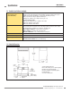
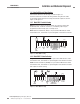
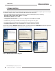
Figure 3-2. MINI-ARRAY emitter and receiver mounting bracket dimensions
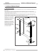
Mounttheemitterandreceiverintheirmountingbrackets(showninFigure3-1),
andpositiontheredlensesofthetwounitsdirectlyfacingeachother.Theconnector
endsofbothsensorsmustpointinthesamedirection.Measurefromoneormore
referenceplanes(i.e.,thefloor)tothesamepointsontheemitterandreceiverto
verifytheirmechanicalalignment.Ifthesensorsarepositionedexactlyverticalor
exactlyhorizontal,acarpenter’slevelmaybeusefulforcheckingalignment.Extending
astraight-edgeorastringbetweenthesensorsmayhelpwithpositioning.Alsocheck
byeyeforline-of-sightalignment.Makeanynecessaryfinalmechanicaladjustments,
andhand-tightenthebrackethardware.SeeSection5forinformationonalignment
indicatorsandtheuseofthealignmentsoftwaresuppliedwiththecontroller.
Connecttheshieldedcablestotheemitterandreceiver,androutethemtothe
controllerlocation.Followthelocalwiringcodeforlow-voltagedccontrolcables.The
samecabletypeisusedforbothemitterandreceiver(twocablesrequiredpersystem).
Cutthecablestolengthaftermakingsuretheyareroutedproperly.Removecablebraid
atthecontrollerconnectionpoints(seeFigure3-4).
3.2 Controller Mounting
ThecontrollermustbeinstalledinsideanenclosurewithaNEMA(orIEC)rating
suitablefortheoperatingenvironment.
MountingdimensionsforthecontrollerareshowninFigure2-2.Thecontrolleris
suppliedwithM3.5x0.6hardwarefordirectmountingtoasurface,oritcanbe
mountedontostandard35mmDINrail.
3.3 Emitter and Receiver Hookups
Emitterandreceivercablesconnectinparalleltocontrollerterminals#4through#8.
Connectthewiresfrombothsensorcables,asfollows:
Terminal4 Brown
Terminal5 Blue
Terminal6 Bare
Terminal7 Black
Terminal8 White
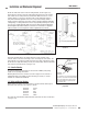
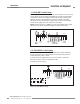
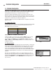
Trimoffthefoilshieldandthebraidedshieldatthepointwherethewiresexitthecable
(seeFigure3-4).
The“drainwire”istheuninsulatedstranded
wirewhichrunsbetweenthebraidedshield
andthefoilshield.Removethefoilshield
andbraidedshieldatthepointwherethe
wiresexitthecable.
Figure 3-4. Emitter/receiver cable
preparation
Tr im braided shield flush
with cable
Tr im foil shield flush
with cable
Uninsulated
drain wire
Emitter or
Receiver
8.1 mm
(0.32") max.
0.5" (13 mm) radius minimum bend
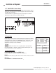
71 mm
2.8"
Figure 3-3. Quick-disconnect cable
clearances