® ® A-GAGE MINI-ARRAY Measuring Light Screen System (MAC Series Controllers) Instruction Manual Features Controller Models MAC-1, MACN-1, MACP-1, MACV-1, MACI-1, MAC16N-1, MAC16P-1 (See Section 1.1 for additional, model-specific features) • Measuring Light Screen system for inspection and profiling applications. • Modular system with compact controller and a variety of BMEL/ BMRL series MINI-ARRAY emitters and receivers. • Sensors available with either 9.5 mm (3/8") or 19.
MINI-ARRAY® Contents Instruction Manual Table of Contents 1. System Overview . . . . . . . . . . . . . . . . . . . . . . . . . . . . . . . . . . . . . . . . page 3 1.1 System Features . . . . . . . . . . . . . . . . . . . . . . . . . . . . . . . . . . . . . . . . . . . . . . . . 4 1.2 System Components . . . . . . . . . . . . . . . . . . . . . . . . . . . . . . . . . . . . . . . . . . . . . 7 2. Specifications . . . . . . . . . . . . . . . . . . . . . . . . . . . . . . . . . . . . . . . . . .
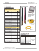
MINI-ARRAY® System Overview Instruction Manual 1. System Overview The Banner A-GAGE® MINI-ARRAY measuring light screen is ideal for applications such as on-the-fly product sizing and profiling, edge-guiding and center-guiding, loop tensioning control, hole detection, parts counting, die ejection verification, and similar uses. A typical MINI-ARRAY System consists of five components: • a Controller module, • an emitter and corresponding receiver, and • two interconnecting cables.
MINI-ARRAY® System Overview Instruction Manual 1.1 System Features Built-in features simplify the operation of the A-GAGE MINI-ARRAY system. Programmable beam blanking accommodates machine components or other fixtures that must remain in or move through the light screen. Blanking is set by using the included configuration software. See Section 5.5.4 for more information.
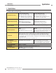
MINI-ARRAY® System Overview Instruction Manual 1.1.1 Model-Specific Features Models MAC-1, MACN-1, and MACP-1 • Supports serial communication with a host computer or PLC via RS-232 or RS-485 interface; enables a computer or PLC to process scan data and/or initiate scans; serial data may be either ASCII or binary. • Up to 15 controllers may be assigned separate IDs and placed on RS-485 party line. • MAC-1: Two outputs: one reed relay and one NPN transistor output; either output may be inverted (i.e.
System Overview MINI-ARRAY® Instruction Manual 1.1.2 Sensing Response Sensing response is a function of the number of beams interrogated (i.e., steps) per scan of the array. The time per step is 55 µs (0.000055 seconds). As a result, dense arrays (i.e., 3/8" beam spacing) yield the highest sensing resolution, while arrays with wider (3/4") beam spacing offer faster sensing response. 1.1.
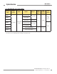
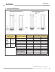
MINI-ARRAY® System Overview Instruction Manual 1.2 System Components Emitter Receiver 1.2.1 Emitter and Receiver Models 19.1 mm (3/4") beam spacing – 16 beams/foot Emitter / Receiver Models Array Length Total Beams BMEL616A / BMRL616A 133 mm (5.25") 8 BMEL1216A / BMRL1216A 286 mm (11.25") 16 BMEL1816A / BMRL1816A 438 mm (17.25") 24 BMEL2416A / BMRL2416A 591 mm (23.25") 32 BMEL3016A / BMRL3016A 743 mm (29.25") 40 BMEL3616A / BMRL3616A 895 mm (35.
MINI-ARRAY® System Overview Instruction Manual 1.2.
MINI-ARRAY® Specifications Instruction Manual 2. Specifications 2.1 Emitter and Receiver Specifications Emitter/Receiver Range 9.5 mm (3/8") Beam Spacing 0.6 to 6.1 m (2 to 20') for sensors < 4' 0.6 to 4.6 m (2 to 15') for sensors > 4' NOTE: Maximum range is specified at the point where 3x excess gain remains. 19.1 mm (3/4") Beam Spacing 0.9 to 17 m (3 to 55') for sensors < 4' 0.9 to 14 m (3 to 45')for sensors > 4' NOTE: Maximum range is specified at the point where 3x excess gain remains.
MINI-ARRAY® Specifications Instruction Manual 2.2 Emitter and Receiver Dimensions With mounting bracket flanges “out” With mounting bracket flanges “in” 38.1 mm Square (1.50") L2 L3 L1 X 2.5 mm (0.10") 18.3 mm (0.72") X (Distance to First Optical Channel) 9.5 mm (3/8") Beam Spacing 38.1 mm (1.50") 19.1 mm (3/4") Beam Spacing 42.9 mm (1.69") Emitter/Receiver Models 10.2 mm (0.40") Housing Length Distance Between Bracket Holes L1 L2 L3 BMEL6..A / BMRL6..A 201.0 mm (7.9") 233.9 mm (9.
MINI-ARRAY® Specifications Instruction Manual 2.3 Controller Specifications Power Requirements 16 to 30V dc @ 1.25 amps max. (see current requirements for sensors); Controller alone (without sensors connected) requires 0.1 amp. Inputs MINI-ARRAY sensor input (5 connections); emitter and receiver wire in parallel to five terminals. GATE input: Optically-isolated, requires 10 to 30V dc (7.5K input impedance) for gate signal.
MINI-ARRAY® Specifications Instruction Manual 2.3 Controller Specifications (continued) Status Indicators (See Section 6.
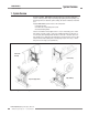
MINI-ARRAY® Installation and Mechanical Alignment Instruction Manual 3. Installation and Mechanical Alignment 3.1 Emitter and Receiver Mounting Banner MINI-ARRAY emitters and receivers are small, lightweight, and easy to mount; the mounting brackets (supplied) allow ±30 degrees rotation. From a common point of reference, make measurements to position the emitter and receiver in the same plane with their midpoints directly opposite each other. Mount the emitter and receiver brackets using the M4 x 0.
MINI-ARRAY® Installation and Mechanical Alignment Instruction Manual Mount the emitter and receiver in their mounting brackets (shown in Figure 3-1), and position the red lenses of the two units directly facing each other. The connector ends of both sensors must point in the same direction. Measure from one or more reference planes (i.e., the floor) to the same points on the emitter and receiver to verify their mechanical alignment.
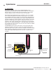
MINI-ARRAY® Installation and Mechanical Alignment Instruction Manual 3.4 Controller Wiring and Output Hookups Cable clearance dimensions for the arrays are shown in Figure 3-3. Controller connections are made via the wiring terminals along the front surface of each module. Emitter and receiver hookups and controller outputs are shown in Figures 3-5 through 3-11. 3.4.1 Model MAC-1 Controller Hookup Output 1: Controller terminals #9 and #10 (OUT1) are reed relay contacts rated at 125V ac/dc max.
MINI-ARRAY® Installation and Mechanical Alignment Instruction Manual 3.4.3 Model MACN-1 Controller Hookup Output 1: Controller terminal #9 (OUT1) is an open-collector NPN transistor switch rated at 30V dc max., 150 mA max. It is protected against overload and short circuits. Alarm: Controller terminal #15 (ALARM) is an open-collector NPN transistor switch rated at 30V dc max., 150 mA max. It is protected against overload and short circuits. Both outputs are current sinking.
MINI-ARRAY® Installation and Alignment Instruction Manual 3.4.5 Model MACI-1 Controller Hookup Current outputs 1 and 2: Controller terminal #9 (I out 1) and #13 (I out 2) are analog current outputs. The load for analog current Output #1 should be connected between an external 16 to 30V dc power supply and terminal #9. The load for analog current Output #2 should be connected between an external 16 to 30V dc power supply and terminal 13.
MINI-ARRAY® Installation and Alignment Instruction Manual 3.4.7 Model MAC16N-1 Controller Hookup Terminals #15 through #30 are open-collector NPN transistor outputs rated at 30V dc max., 150 mA max. They are protected against overload and short circuits. All outputs are current sinking. Controller terminal #15 (output #16) may be used as an output or as an alarm. Whenever this output is active, the red Alarm LED is ON.
MINI-ARRAY® Instruction Manual Software Installation 4. Software Installation The Parameter Setup Software CD includes an installation program that quickly and easily loads the MINI-ARRAY configuration program into the computer. The MINI-ARRAY configuration program requires approximately 50 MB of hard disk space. Install as follows: 1. Use the Parameter Setup Software CD included with the controller, or download (www.bannerengineering.
MINI-ARRAY® Controller Configuration Instruction Manual 5. Controller Configuration Configuration of the MINI-ARRAY controller is accomplished with a Windows® menustyle procedure, using the Banner-supplied software and a PC-compatible computer running Windows® A serial data connection is made between the computer and the DB9 connector on the controller (see Figure 3-12). Parameter Setup Files (PSF) are programmed configurations that can be stored in the control module’s non-volatile memory.
MINI-ARRAY® Controller Configuration Instruction Manual 5.3 Alignment The Alignment screen (Figures 5-3 and 5-4), identifies the location of the first and last beams made (clear) and broken (blocked), plus the total number of beams made and broken. The beams are numbered in sequence from the cable end of the sensors to the top end. This is valuable during setup, for analyzing exactly what is being seen by the light screen.
Controller Configuration MINI-ARRAY® Instruction Manual 5.4 Parameter Setup Files (PSFs) The input and output response of the MAC controller is programmed using the PSF Configuration screen shown in Figure 5-5 (models MAC-1, MACN-1, MACP-1, MACV-1, and MACI-1) and Figure 5-6 (models MAC16N-1 and MAC16P-1). To access the PSF Configuration screen, select Edit PSF under the MINI-ARRAY Main menu (Figure 5-2), or press the F4 key. The chart on page 24 lists the programmable functions. Section 5.
MINI-ARRAY® Instruction Manual Controller Configuration 43989 Figure 5-7. Use the PSF Configuration screen to program each control module individually (see Figure 5-10 for 16-output models) Banner Engineering Corp. • Minneapolis, MN U.S.A. www.bannerengineering.com • Tel: 763.544.3164 P/N 43298 rev.
MINI-ARRAY® Controller Configuration Instruction Manual Parameter Setup Files Available for Each Controller Model Analysis Mode Selection (See Section 5.5.3 for descriptions of these Analysis Modes.
MINI-ARRAY® Controller Configuration Instruction Manual 5.5 Creating New Parameter Setup Files (PSFs) 5.5.1 Analysis Mode Assignment One or two Measurement Analysis modes may be programmed. Meas1 or Meas2 may be assigned to one or both outputs (Figure 5-8). If ALL is selected in either Analysis mode, all of the scanning information is sent via the serial connection to a host computer or PLC. The selection of ALL does not allow output assignments to be made to that measurement mode.
MINI-ARRAY® Controller Configuration Instruction Manual Hysteresis (Low and High) determines how much change must occur at each set point to cause the associated output to change state. Hysteresis avoids unstable output conditions (e.g., chattering of the output) when the scanning condition exactly matches one of the set points. The default setting for hysteresis is one beam less than the Low Set Point and one beam more than the High Set Point.
MINI-ARRAY® Controller Configuration Instruction Manual MACV-1 and MACI-1 — Analog Outputs The MACV-1 and MACI-1 Controllers offer two independent analog outputs. See Figure 5-9. For Analog Output #1 and Analog Output #2, each output is assigned to one of six analysis modes, which are selected via the Edit PSF Screen of the supplied software. Once the Analysis Mode Selection is specified for Meas1 and Meas2, the Analog Output can specified via the Analog Output choices.
MINI-ARRAY® Controller Configuration Instruction Manual 5.5.3 Analysis Mode Selection Last Beam Made, First Beam Made The MINI-ARRAY controller is a versatile microcontroller-based module that may be configured using a PC-compatible computer running Windows® and the Banner-supplied software via the built-in RS-232 or RS-485 interface.
MINI-ARRAY® Controller Configuration Instruction Manual 5.5.4 Blanking Specifications A Blanking feature allows areas of the array to be blanked (made blind to activity within an area). Models MAC-1, MACP-1, MACN-1, MACV-1, and MACI-1 Blanking specifications allow either one or two areas of the array to be blanked (made blind to activity within that area). Beams are numbered from the bottom (cable end) of the sensors to the top of the sensors.
MINI-ARRAY® Controller Configuration Instruction Manual Auto Blanking selects all blocked channels for blanking. When the Auto Blanking feature is selected, the settings may be accepted or aborted. Abort Auto Blanking cancels Auto Blanking. File Save and File Retrieve allow the user to save and retrieve blanking data to a file. The OK button saves the new blanking configuration to the controller. After the OK button is selected, Restore Controller Settings will reflect the new blanking configuration.
MINI-ARRAY® Controller Configuration Instruction Manual 5.5.5 Scanning Methods The control module may be configured for one of four available scanning methods (see Figure 5-16): Straight Scan is the default mode in which all beams are scanned in sequence from the bottom end (cable end) to the top end of the sensors. Interlaced Scan alternates a straight scan with a slanted-beam scan. A slanted-beam Figure 5-16.
MINI-ARRAY® Controller Configuration Instruction Manual 5.5.6 Control Mode Selection The controller can be programmed for Continuous scanning, Gated scanning, or for Host mode. The module offers an optically-isolated Gate input, which is energized by application of 10 to 30V dc. Gating is typically accomplished using a dc presence sensing device. Host mode allows the array to be gated by a host computer or programmable logic controller (PLC).
MINI-ARRAY® Controller Configuration Instruction Manual 5.7 PSF Assignment and Storage The screens shown in Figures 5-20 through 5-22 are for MAC-1, MACP-1, MACN-1, MACV-1, and MACI-1 Controllers. The screen layouts for MAC16N-1 and MAC16P-1 are functionally the same and do not need to be shown separately. PSF commands are located in the lower right corner of the PSF Configuration screen.
MINI-ARRAY® Controller Configuration Instruction Manual Retrieving a PSF from Disk To retrieve a filed PSF, select File Retrieve PSF. The FileBox subscreen will appear (Figure 5-22). Select the desired PSF from the File Name list and then select OK or press the Enter key. The selected PSF will load to the PSF Configuration screen and can be loaded into the controller using the Send PSF command. Figure 5-22.
MINI-ARRAY® System Operation Instruction Manual 6. System Operation 6.1 Sensor Operating Status Indicators NOTE: Status indicators appear to “freeze” if the controller has been configured for the Gate or the Host Mode (see Section 5.5.6), and there is no signal to cause a scan update. Emitter (Figure 6-1) The red LED ON indicates that the emitter has power applied and is functioning properly. If the red LED is OFF, there has been an emitter failure.
MINI-ARRAY® System Operation Instruction Manual 6.2 Controller Operating Status Indicators Output 1 (labeled OUT1, V out, I out, OUT or OUT 1 depending on model) Red Alarm Red Models MAC-1, MACP-1, MACN-1, MACV-1, MACI-1: displays the status of Output #1 Models MAC16N-1 MAC16P-1: displays the status that at least one output is active Models MAC-1, MACP-1, MACN-1, MACV-1, MACI-1: displays the status of Output #2.
MINI-ARRAY® System Operation Instruction Manual 6.3 Diagnostics Program Emitter or receiver problems may be further diagnosed using the diagnostics routine, which is included with the MINI-ARRAY software. Launch the program by selecting Diagnostics... under the MINI-ARRAY menu (see Figure 6-3), or press the F2 key. The Diagnostics screen (Figure 6-4) displays the type of each emitter and receiver module (Board) and its functional status (State).
System Operation MINI-ARRAY® Instruction Manual Banner Engineering Corp. • Minneapolis, MN U.S.A. 38 P/N 43298 rev. E www.bannerengineering.com • Tel: 763.544.
MINI-ARRAY® Appendix Instruction Manual Appendix. Host Mode Command and Serial Data Format Host Mode Command The MINI-ARRAY controller can communicate with a computer or PLC via either an RS-232 connection (all models) or RS-485 connection (discrete-output models). See hookup information in Section 3.4. The host can respond to output from the controller when the controller is programmed for either the Continuous or Gate control mode (see Section 5.5.6). Alternately, the host can control sensor scanning.
MINI-ARRAY® Appendix Instruction Manual ASCII Format Data Transmission There are two ASCII formats. The one used depends upon which measurement modes are selected. For the ALL measurement mode, each data byte is presented in an eight bit ASCII format which conveys the status of four consecutive channels (four consecutive beams). Each subsequent byte conveys the status of the next four channels, until the status of all channels is reported.
MINI-ARRAY® Appendix Instruction Manual Figure A-2 shows that the binary transmission has three independent options. These options are independently selected and are used to custom-configure the serial data format. The Suppress Clear Data option is applicable when the sensor is unobstructed. While the sensor is blocked, serial data is transmitted; once the sensor is unobstructed, the “clear” data is transmitted once, and then no further data transmission occurs until the sensor is again blocked.
Notes MINI-ARRAY® Instruction Manual Banner Engineering Corp. • Minneapolis, MN U.S.A. 42 P/N 43298 rev. E www.bannerengineering.com • Tel: 763.544.
Banner Engineering Corp Limited Warranty Banner Engineering Corp. warrants its products to be free from defects in material and workmanship for one year following the date of shipment. Banner Engineering Corp. will repair or replace, free of charge, any product of its manufacture which, at the time it is returned to the factory, is found to have been defective during the warranty period.