
Instruction Manual


12 P/N 117167 rev. A
Banner Engineering Corp. • Minneapolis, MN U.S.A.
www.bannerengineering.com • Tel: 763.544.3164
MINI-ARRAY
®
Two-Piece Measuring Light Screen
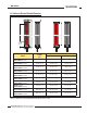
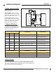
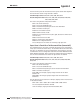
3.2 Emitter and Receiver Hookups
Connect the emitter and receiver cables as
shown in Figure 3-6.
Receiver Output 1: (OUT1) is an open-
collector NPN transistor switch rated at
30V dc max., 150 mA max. It is protected
against overload and short circuits.
Receiver Alarm: (ALARM) is an open-
collector NPN transistor switch rated at
30V dc max., 150 mA max. It is protected
against overload and short circuits.
Both outputs are current sinking.
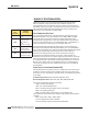
3.3 Diagnostic LED Indicators
The emitter has a single Red status LED.
The receiver’s three LEDs (Green, Yellow,
and Red) are used in combination to
diagnose system status.
L
LÕ
«
Ü
}Þ
Þi
À`
À`
}
}
L>Ài
L
LÕ
«
Ü
}Þ
Þi
³
q
£ÈÎä6Ê`V
*°-°Ê6ʳ
*°-°Ê6Êq
-9 ʳ
-9 Êq
"1/£
"1/ÓÉ,
Ê{nxʳ
Ê{nxÊq
- -
*°-°Ê6³
*°-°Ê6q
-9 ʳ
-9 Êq
,iViÛiÀ ÌÌiÀ
>`Ê£
>`ÊÓ
Ê*ÜiÀ
-Õ««Þ
ÌÊiÝÌiÀ>
{nx
`iÛViÊÌiÀ>
ViVÌ
Figure 3-5. A-GAGE MINI-ARRAY Two-Piece Measuring Light Screen hookup diagram
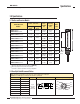
Receiver LED Condition
System Status Possible Action
Green Yellow Red
ON OFF OFF Emitter/receiver pair aligned • None
ON ON OFF Emitter/receiver pair aligned with dirty lens
• Clean lenses
• Align emitter and receiver
OFF OFF ON Emitter/receiver pair blocked • None
OFF ON ON Emitter/receiver pair blocked with dirty lens
• Clean lenses
• Align emitter and receiver
ON ON ON Receiver error • Replace receiver
ON
Flashing
@ 2 Hz
OFF Degraded mode; emitter/receiver pair aligned
• Clean lenses
• Align emitter and receiver*
OFF
Flashing
@ 2 Hz
ON Degraded mode; emitter/receiver pair blocked
• Clean lenses
• Align emitter and receiver*
Flashing
@ 2 Hz
OFF
Flashing
@ 2 Hz
Emitter is not functioning • Connect emitter
Emitter LED Condition Emitter Status Possible Action
Red ON Emitter operating properly • None
Red Flashing @ 1 Hz Emitter is degraded • Replace emitter
Red Flashing @ 5 Hz Emitter has power, but receiver is not hooked up • Connect or replace receiver
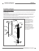
3.4 Optical Alignment
After connecting the cables per Figure 3-5, apply 16-30V dc power to the sensor.
Rotate the emitter and/or receiver as necessary to align them. When aligned, the
receiver Green LED is ON. Align the emitter and receiver until the receiver’s Green
LED is ON and the Yellow and Red LED are OFF.
Installation and Alignment
* If after cleaning the emitter and receiver lenses, the emitter diagnostic is solid Red, consider replacing the receiver.