
User Manual

Banner Engineering Corp., 9714 Tenth Ave. No., Minneapolis, MN USA 55441 • Phone: 763.544.3164 • www.bannerengineering.com • Email: sensors@bannerengineering.com
A-GAGE
®
MINI-ARRAY
®
Two-Piece Measuring Light Screen
P/N 119169 rev. A
WARRANTY: Banner Engineering Corp. warrants its products to be free from defects for one year. Banner Engineering Corp. will
repair or replace, free of charge, any product of its manufacture found to be defective at the time it is returned to the factory during the
warranty period. This warranty does not cover damage or liability for the improper application of Banner products. This warranty is in
lieu of any other warranty either expressed or implied.
Installation
Guide
Supply Voltage and Power
16 to 30V dc. Maximum power 12 watts.
Supply Protection Circuitry
Protected against transient voltages and reverse polarity
Discrete Output Configuration
2 Discrete Outputs: Output 1 and Output 2. Outputs can be configured as either open collector
NPN or PNP transistors. For the vehicle separation application, the outputs are factory configured
as NPN outputs.
Discrete Output (either NPN or PNP) ratings: Rated at 30V dc max, 150 mA max
load, short circuit protected
OFF-State Leakage Current: <10 µA @ 30V dc
ON-State Saturation Voltage: <1V @ 10 mA, <1.5V @ 150 mA
Serial Data Outputs
EIA-485 interface Baud rate 9600, 19.2 K, 38.4 K
8 data bits, 1 start bit, 1 stop bit, no parity
Controller Programming
Via EIA-485 to PC-compatible computer running Windows® 98, NT, ME, XP, 2000 Operating
System
Emitter/Receiver Range
Sensors < 1220 mm (4') long: 0.9 to 16.5 m (3' to 55')
Sensors ≥ 1220 mm (4') long: 0.9 to 13.5 m (3' to 45')
NOTE: Maximum range is specified at the point where 3x excess gain remains.
Minimum Object Sensitivity
Interlaced Mode: 25.4 mm (1.0")* Other Scan Modes: 38.1 mm (1.5")
*Assumes sensing is in middle one-third of scanning range.
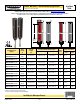
Sensor Scan Time
See table in front page. NOTE: Worst-case response time is twice the scan time.
Cable Connections
See hookup diagram above. QD cables available separately.
Emitter and receiver cables may not exceed 80 m (250') each.
Status Indicators
Emitter: Red LED lights for proper operation
Receiver: Green – sensors aligned (> 3x excess gain)
Yellow – marginal alignment (1x-3x excess gain)
Red – sensors misaligned or beam(s) blocked
Environmental Rating
NEMA 4,13 (IEC IP65); UL Type 1 enclosure
Construction
Aluminum housing with black anodized finish; acrylic lens cover
Operating Conditions
Temperature: -40° to +70°C (-40° to +158°F)
Maximum relative humidity: 95% (non-condensing)
Certifications
Application Notes
• The emitter and receiver sync lines (pink and white wires) will be damaged if connected to
the power supply.
• The receiver EIA-485 interface (red and green wires) will be damaged if connected
to the power supply.
Additional information on this product is immediately available online at www.bannerengineering.com
View or download additional information, including diagnostics, mounting/alignment, applications, and serial communication data formats.
For further assistance, contact a Banner Engineering Applications Engineer at (763) 544-3164 or (888) 373-6767.
Specifications
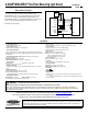
Emitter and Receiver Hookups
Connect the emitter and receiver cables as shown in the figure at right.
Receiver Output 1: (OUT1) is an open-collector NPN transistor switch rated at
30V dc max., 150 mA max. It is protected against overload and short circuits.
Receiver Alarm: (ALARM) is an open-collector NPN transistor switch rated at 30V
dc max., 150 mA max. It is protected against overload and short circuits.
Both outputs are current sinking.
L
LÕ
«
Ü
}Þ
Þi
À`
À`
}
}
L>Ài
L
LÕ
«
Ü
}Þ
Þi
³
q
£ÈÎä6Ê`V
*°-°Ê6ʳ
*°-°Ê6Êq
-9 ʳ
-9 Êq
"1/£
"1/ÓÉ,
Ê{nxʳ
Ê{nxÊq
- -
*°-°Ê6³
*°-°Ê6q
-9 ʳ
-9 Êq
,iViÛiÀ ÌÌiÀ
>`Ê£
>`ÊÓ
Ê*ÜiÀ
-Õ««Þ
ÌÊiÝÌiÀ>
{nx
`iÛViÊÌiÀ>
ViVÌ
A-GAGE MINI-ARRAY Two-Piece Measuring Light Screen hookup diagram
WARNING . . .
Not To Be Used for Personnel Protection
Never use these products as sensing devices for personnel protection. Doing so could lead to serious injury or death.
These sensors do NOT include the self-checking redundant circuitry necessary to allow their use in personnel safety applications. A sensor failure or malfunction can
cause either an energized or de-energized sensor output condition. Consult your current Banner Safety Products catalog for safety products which meet OSHA, ANSI and
IEC standards for personnel protection.