
Owner manual


P/N64118rev.B
System Description
6
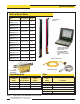
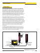
Figure 1-2. A-GAGE High-Resolution MINI-ARRAY System features
1.2 System Features
Built-infeaturessimplifytheoperationoftheA-GAGEHigh-ResolutionMINI-ARRAY
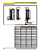
system.High-resolutionemittersandreceivers,availablein12lengths,featuretwo
closelyspacedcolumnsofbeamstoprovideaprecise,high-resolutionlightscreenfor
exactingapplications.TheAlignmentroutineautomaticallyequalizestheexcessgainof
eachbeamforreliable2.5-mm(0.10")objectdetectionthroughoutthearrayandstores
thisdatainnon-volatilememory.TheAlignmentroutineneednotbeperformedagain
unlessthesensingapplicationchanges,oriftheemitterand/orreceiverismoved.
Programmablebeamblankingaccommodatesmachinecomponentsorotherfixturesthat
mustremaininormovethroughthelightscreen.Blankingmaybesetautomaticallyas
partoftheinitialsetup,orbyusingtheincludedconfigurationsoftware.
Built-indiagnosticprogrammingandeasy-to-seeindicatorsonthesensorsandthe
controlmodulemakealignmentandtroubleshootingeasy(Figure1-2).Theemitterhas
aredLEDthatsignalsproperoperation.ThereceiverhasthreebrightLEDs:green
signalsthatthesensorsareproperlyaligned;yellowsignalsmarginalalignment;and
redsignalsmisalignmentorablockedcondition.Thecontrolmodulehasfourstatus
indicators:3redLEDssignaldiscreteoutput#1conducting(seesection5.3.5formore
informationonoutputs),Alarmoutput(discreteoutput#2)conducting,andgatesignal
received;agreenLEDsignalsthatthesensorsareproperlyaligned.AsegmentedLED
DiagnosticsIndicatorprovidesdetailedsystemstatususingsingle-digitcodes;a
“period”intheindicatorwindowindicatesthepresenceofblanking.Akeytothe
diagnosticscodesisprintedonthesideofthecontrolmoduleforsimplified
troubleshooting.
TheA-GAGEHigh-ResolutionMINI-ARRAYSystemprovidesawideselectionof
sensingandoutputoptions,including:measurement(“scananalysis”)modesand
scanningmethodsthatcandeterminethetargetobject’slocation,overallsize,total
heightortotalwidth.Scanningmaybecontinuousorcontrolledbyahostprocess
controlleroragatesensor.Upto15systemsmaybenetworked.
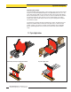
High-Resolution Emitter
DIN-Rail-Mountable Control Module
High-Resolution Receiver
HIGH RESOLUTION MINI-ARRAY CONTROLLER
ALIGNMENT
SWITCH
POWER
POWER
DIAGNOSTICS
INDICATOR
2 - TX
3 - RX
5 - COM
RS-232
MAHCVP-1
OUTPUT
ALARM
GATE
ALIGN
1
+–
+
–
16-30V dc
1A MAX
10-30VDC
GATE
D OUT 1
150mA MAX
0-10VOLTS
25mA (MAX)
V OUT 1
EMTR RCVR
2 3 4 5 6 7 8 9 10 11 12 13 14 15 16 17 18 19 20
F1
+12V COM DRN T/RT/R
BR BU BK WH
TX TX
+
–
10-30VDC
ALIGN
0-10VOLTS
25mA (MAX)
V OUT 2
+V
ALARM
150mA MAX
+V
7.6 mm (0.30")
2.5 mm
(0.10")
5.1 mm
(0.20")
Diagnostics Indicator
Alignment Button
Red Discrete Output #1 LED
Red
Operational
LED
Green Alignment LED
Red Blocked LED
Yellow Marginal
Alignment LED
Red Alarm (Discrete Output #2) LED
Red Gate LED
Green Align LED
RS-232 Port
Banner Engineering Corp. •Minneapolis,U.S.A.
www.bannerengineering.com•Tel:763.544.3164