
Owner manual


P/N64118rev.B
System Diagnostics
32
Banner Engineering Corp. •Minneapolis,U.S.A.
www.bannerengineering.com•Tel:763.544.3164
6. System Diagnostics
Systemdiagnosticsmaybeperformedusingthestatusanddiagnosticsindicatorsonthe
controlmoduleandsensors,orbyusingtheDiagnosticssoftwareroutine,ora
combinationofthetwo.
6.1 Diagnostics Indicators
NOTE:Statusindicatorsappearto“freeze”ifthecontrollerhasbeenconfiguredforGate
orHostmode(Section5.3.2),andnosignalispresenttocauseascanupdate.
DIAGNOSTICS
Error No. Error Type/Action
– System is OK
A / b
Align / blank
• Status
1
Output Short
• Checkoutputload&wiring
2
E / R Mismatch
• Systemmustusesamelength
emitterandreceiver
3
Receiver Error
• Checkreceivercable
• Replacereceiver
4
Emitter Error
• Checkemittercable
• Replaceemitter
5
Serial Comm
• Checkserialcable
6
EEPROM
• ReconfigurePSF
• Replacecontrolmodule
• Reconfigureblanking
7
CPU Error
• Replacecontrolmodule
8
Null / Span
• Status
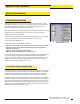
Figure 6-2. Key to System Diagnostics
Indicator codes
Red
Operational
LED
Green Alignment LED
Red Blocked LED
Yellow Marginal
Alignment LED
High-Resolution
Emitter
High-Resolution
Receiver
DIN-Rail-Mountable
Control Module
HIGH RESOLUTION MINI-ARRAY CONTROLLER
ALIGNMENT
SWITCH
POWER
POWER
DIAGNOSTICS
INDICATOR
2 - TX
3 - RX
5 - COM
RS-232
MAHCVP-1
OUTPUT
ALARM
GATE
ALIGN
1
+–
+
–
16-30V dc
1A MAX
10-30VDC
GATE
D OUT 1
150mA MAX
0-10VOLTS
25mA (MAX)
V OUT 1
EMTR RCVR
2 3 4 5 6 7 8 9 10 11 12 13 14 15 16 17 18 19 20
F1
+12V COM DRN T/RT/R
BR BU BK WH
TX TX
+
–
10-30VDC
ALIGN
0-10VOLTS
25mA (MAX)
V OUT 2
+V
ALARM
150mA MAX
+V
Diagnostics Indicator
Alignment Button
Red Discrete Output #1 LED
Red Alarm (Discrete Output #2) LED
Red Gate LED
Green Align LED
RS-232 Port
Figure 6-1. A-GAGE High-Resolution MINI-ARRAY System diagnostics and status indicators
Bright,easy-to-seeLEDindicatorsonbothsensorsandonthefrontpanelofthe
controlmoduleprovideanongoingdisplayofthesystem’soperatingstatus.
Control Module:
OUTPUT:(red)displaysthestatusofDiscreteOutput#1.
ALARM: (red)displaysthestatusofDiscreteOutput#2.Thisoutputmaybeassigned
toananalysismode,oritmaybeusedasaSystemDiagnosticsalarmorasaTrigger
alarmtogateanotherA-GAGEHigh-ResolutionMINI-ARRAYSystem.
GATE:(red)displaysthestatusoftheGateinput.
ALIGN: (green)indicatesproperemitter/receiveralignmentandaclear,unblockedlight
screen.ThisindicatorisONwheneitherthegreenorboththegreenandyellowLEDs
ofthereceiverareON.