
Owner manual


P/N64118rev.B
Control Module Configuration
28
Banner Engineering Corp. •Minneapolis,U.S.A.
www.bannerengineering.com•Tel:763.544.3164
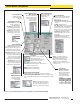
5.3.7 Discrete Output Configuration (Analysis Mode Assignment)
Discreteoutputs#1and#2(“Alarm”)mayeachbeindividuallyassignedtooneofthe
ScanAnalysisModesprogrammedinsection5.3.4(seeFigures5-16and5-22).
NexttoeachdiscreteoutputassignmentmenuareLowandHigh
Set Pointboxes.Thenumberineachboxidentifiesabeaminthe
array(beam#1beingclosesttothecabledendoftheemitterand
thereceiver).TheLowandHighSetPointsmaybechangedby
clickingonaboxandenteringanewnumber.
WhentheselectedScanAnalysisModeinvolvesfirstorlastbeam
blockedormade(unblocked),theassignedoutputwillenergize
whenthebeamidentifiedduringascanfallswithintherangeof
thesetpoints.WhentheScanAnalysisModeinvolvestotalbeams
blockedormade,thatassignedoutputwillenergizewhenthe
valueoftotalbeamscountedduringascanfallswithintherange
ofthesetpoints.
Notethatthepull-downmenususedforassignmentoftheScan
AnalysisModestothediscreteoutputsincludetwo“Inverted”selections.Wheneither
MEAS1 InvertedorMEAS2 Invertedisselected,thatdiscreteoutputwillde-energize
(turnOFF)wheneverascananalysisvaluefallswithintherangeofthesetpoints.
Hysteresisvaluesforeachendofthesetpointrangemayalsobeset(Figure5-22).
Hysteresisdeterminestheamountofchangethatmustoccurateachsetpoint(High
andLow)tocausetheassociatedoutputtochangestate.Hysteresisprevents
unstableoutputconditionswhenthescananalysisvalueexactlymatchesoneofthe
setpoints.ThedefaulthysteresissettingisonebeamlessthantheLowSetPointand
onebeammorethantheHighSetPoint.
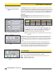
Scan #Providesanotherway,inadditiontohysteresissettings,tosmoothoutput
response.Outputsareupdatedonlyaftertheselectednumberofidentical(withinthe
hysteresislimits)scans.Themenuallowsselectionoffrom1to9scans.Fordiscrete
outputs,thescananalysisvaluemuststayeitherinsideoroutsidethehysteresis
limitsforalloftheselectednumberofconsecutivescans,inorderfortheoutputto
respond.SeeFigure5-23.
Alarm and Trigger
Discreteoutput#2(only)hastwoadditionaloptions:AlarmandTrigger.
Alarm:Output#2energizeswhenevertheSystemdetectsasensorerror(suchasa
disconnectedcable)orwhenevertheexcessgainofoneormorebeamsbecomes
marginal.
Trigger: canbeusedtogateasecondcontrolmodulewhenContinuousScanMethod
isalsoused.Whenthecontrolmoduleisinstraightscanningmode,Trigger Channel
Numberdefinesthebeamnumberduringascanatwhichthetriggeroutputwilloccur
(Figure5-23).TheTriggeroutputisa100microsecond(0.0001sec.)pulse.Ifthe
controlmoduleissetforsingleordoubleedgescan,theTriggerpulsewillcomeat
theendofthescan(Trigger Channel Numberwillbeignored).
Figure 5-23. Scan # (PSF Configuration
Screen)
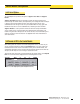
Figure 5-24. Trigger Channel
Figure 5-22. Assigning an Analysis Mode to each Discrete output
(PSF Configuration screen). Alarm and Trigger
output options are available only for Discrete
Output #2.