
Owner manual


P/N64118rev.B
Control Module Configuration
26
5.3.4 Scan Analysis Mode Selection
Thecontrolmodulemaybeprogrammed,ifdesired,foranyoneortwoofsevenScan
Analysis(measurement)Modes.Eachselectedmodemaybeassignedindividuallyto
anoutput(seesection5.3.5or5.3.6).Thebeamsinthearrayarenumberedin
sequence,withbeam#1locatedatthecabledendoftheemitterandthereceiver.
“Beam Location” Modes
• First Beam Blocked (FBB): ThecontrolmoduleidentifiesthelocationoftheFirst
BeamBlocked.
• First Beam Made (FBM):ThecontrolmoduleidentifiesthelocationoftheFirst
BeamMade(unblocked).
• Last Beam Blocked (LBB):ThecontrolmoduleidentifiesthelocationoftheLast
BeamBlocked.
• Last Beam Made (LBM):ThecontrolmoduleidentifiesthelocationoftheLast
BeamMade(unblocked).
• Middle Beam Blocked (MBB):Thecontrolmoduleidentifiesthelocationofthe
MiddleBeamBlocked,midwaybetweenthefirstandlastbeamsblocked.
“Beam Total” Modes
• Total Beams Blocked (TBB): Thecontrolmoduletotalsthenumberofblocked
beams.
• Total Beams Made (TBM): Thecontrolmoduletotalsthenumberofmade
(unblocked)beams.
•Contiguous Beams Blocked (CBB):Thecontrolmoduleidentifiesthelargestnumber
ofconsecutivelyblockedbeams.
•Contiguous Beams Made (CBM):Thecontrolmoduleidentifiesthelargestnumber
ofconsecutivelymadebeams.
•Transitions (TRN):Thecontrolmodulecountschangesfromblockedtoclearand
cleartoblocked.Forinstance,ifbeams6-34areblocked,thenthereisaclear-to-
blockedtransitionfrombeam5tobeam6,andablocked-to-cleartransitionfrom
beam34tobeam35.Transitionmodecanbeusedtocountobjectswithinthearray.
TheAnalysisMode(s)programmedmaybeassignedtoanyoneoftheavailable
outputs(seeFigure5-18).EachoutputcanbesetforMEAS1, MEAS2, MEAS1
InvertedorMEAS2 Inverted.
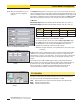
5.3.5 Analog Output Configuration (Analysis Mode Assignment)
Analogoutputs#1and#2mayeachbeassignedtooneoftheanalysismodes
describedinsection5.3.4.WhentheselectedScanAnalysisModeinvolvesfirstor
lastbeamblockedormade(unblocked),theassignedoutputwillvaryinproportionto
thebeamnumberidentifiedduringascan.WhentheScanAnalysisModeinvolves
totalbeamsblockedormade,thatassignedoutputwillvaryinproportiontothetotal
beamscountedduringascan.
Notethatthepull-downmenususedforassignmentoftheScanAnalysisModesto
theanalogoutputsincludetwo“Inverted”selections.WheneitherMEAS1 Invertedor
MEAS2 Invertedisselected,thatanalogoutputwilldecreaseasthemeasurement
modevalueincreases.Aninvertedoutputwillbeatfullscale(Spanvalue)whenthe
scananalysisvalueiszero;andatmaximumscananalysisvalue,theoutputwillbeat
theNullvalue.
Figure 5-18. Assigning an Analysis Mode to
each Analog Output
(PSF Configuration screen)
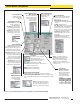
Figure 5-17. Examples of MINI-ARRAY scan
analysis modes
Figure 5-16. Scan Analysis Mode Selection
(PSF Configuration screen)
Last Beam Made (LBM)
First Beam Made (FBM)
Receiver
Emitter
8
16
24
32
40
48
Last Beam Blocked (LBB)
First Beam Blocked (FBB)
Receiver
Emitter
8
16
24
32
40
48
Total Beams Made (TBM)
Total Beams Blocked (TBB)
Receiver
Emitter
8
16
24
32
40
48
InLastBeamBlockedmode,
lastbeamis#43of48
InFirstBeamBlockedmode,
firstbeamis#15of48
InLastBeamMademode,
lastbeamis#37of48
InFirstBeamMademode,
firstbeamis#26of48
InTotalBeamsMademode,
34of48possiblebeamsare
made
InTotalBeamsBlockedmode,
14of48possiblebeamsare
blocked
Banner Engineering Corp. •Minneapolis,U.S.A.
www.bannerengineering.com•Tel:763.544.3164