
Owner manual


P/N64118rev.B
Control Module Configuration
24
Banner Engineering Corp. •Minneapolis,U.S.A.
www.bannerengineering.com•Tel:763.544.3164
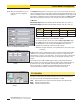
5.3.3 Scanning Method
Thecontrolmodulemaybeconfiguredforoneofthreescanningmethods(Figure5-12):
• Straightscan
• Single-Edgescan
• Double-Edgescan
Straight Scanisthedefaultmodeinwhichallbeamsarescannedinsequencefromthe
bottomend(cableend)tothetopendofthearray.Thisscanningmethodrequiresthe
longestscantimesandprovidesthesmallestobjectdetectionsize(2.5mm,0.1"diameter).
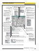
Single-Edge Scanisusedtomeasuretheheightofasingleobject.Agoodapplication
forthisscanningmethodisboxheightmeasurement.ForSingle-EdgeScan,theSystem
alwaysactivatesthefirstbeamchannel(nearestthecableend,or“bottom”).Ifthefirst
beamisblocked,thesensorwillperformabinarysearchtohuntforthelastbeam
blocked.Single-EdgeScanworksasfollows:
1. Thereceiverscansonlythebottombeamuntilthatbeamisblocked.
2. Whenthebottombeamisblocked,thesensorlookstoseewhetherthemiddlebeam
isblockedormade(unblocked).
3. Ifthemiddlebeamismade(unblocked),thesensorchecksthebottomquarterbeam;
ifthemiddlebeamisblocked,thesensorchecksthetopquarterbeam.(Thisiscalled
abinarysearch;seeFigure5-13.)
4. Thisroutinecontinuesto“narrowthefield”untiltheedgeisfound.
Notethatthereceiveralwayschecksthebottombeamfirst,andonlyifthatbeamis
blockeddoesthebinarysearchcontinue.Therefore,Single-EdgeScanwillnotworkin
instanceswhereanitemthatdoesnotblockthefirstbeamistobemeasured.Single-Edge
Scanisalsoineffectiveiftheobjectdoesnotpresentacontinuousblockedpattern.In
otherwords,Single-EdgeScanisusedforsingle,solidobjectsthatblockthefirstbeam.
Figure 5-12. Scanning Method selections
(PSF Configuration screen)
DIAGNOSTICS
E
rro
r N
o
.
Error Typ
e
Erro
r N
o
.
Error T
ype
—
Sy
stem
O
K
4Em
itter Error
1
A
lign
/ b
lan
k
5 Serial C
o
m
m
2O
u
tp
u
t Short
6 E
EP
RO
M
3
E / R
M
ism
a
tch
7
C
P
U
Erro
r
4
R
eceiver Error
8 N
ull / S
p
an
1
P
O
W
E
R
2 - TX
3 - R
X
5 - C
O
M
A
LIG
N
M
EN
T
S
W
IT
CH
D
IA
G
N
O
STIC
S
IN
D
ICA
TO
R
RS
-232
M
A
H
CN
-1
H
IG
H R
ES
OLU
TIO
N
M
IN
I-A
RR
A
Y CO
N
TR
O
LLER
2 3 4
5 6 78
9
10
111
2 13
141
5
16 17
1
8
19 20
1
+
N
C
N
C
1
0
-
3
0
V
d
c
G
A
T
E
N
C
T
X T
X
+
1
2
V
B
R
E
M
T
R
R
C
V
R
B
U B
K
5
W
i
r
e
s
W
H
3
0
V
1
5
0
m
A
M
A
X
O
U
T
P
U
T
#
1
C
O
M
D
R
N
T
/R
T
/
R
1
6
-
3
0
V
d
c
1
A
M
A
X
P
O
W
E
R
2
3 4
5 6 7
8
9 1
0 1
1
1
2
1
3
1
4 1
5
1
6
1
7 1
8 1
9
2
0
OUTPUT
ALARM
GATE
ALIGN
–
+
–
F
1
3
0
V
(
M
A
X
)
1
5
0
m
A
M
A
X
A
L
A
R
M
1
0
-
3
0
V
d
c
A
L
I
G
N
R
S
-
4
8
5
+
–
High-Resolution
Emitter
MAHCN-1
Control Module
High-Resolution
Receiver
Beam #1 of 64
Blocked
Beam #48
Clear
Beam #32
Blocked
Beam #44
Clear
Beam #40
Blocked
Beam #42
Blocked
Beam #43
Blocked
Step #2Step #1 Step #3
Step #4 Step #5 Step #6 Step #7
Figure 5-13. Finding an edge using a binary search