
Owner manual


23
Banner Engineering Corp. •Minneapolis,U.S.A.
www.bannerengineering.com•Tel:763.544.3164
P/N64118rev.B
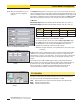
5.3.1 Selected Controller and Serial Communication
TheSelectedControllerboxdisplaysinformationaboutthecontrolmodulebeing
configured.TwoofthesesettingsmaybechangedintheSerialCommunicationbox.
Thesettingsselectedanddisplayedintheseboxesarethoseusedtoidentifythe
controlmoduleduringthePingroutine(section5.1.1).
Controller ID(assignedaletter,‘A’through‘O’)isusedtoidentifyeachindividual
controlmodulewhenmultiplediscrete-outputcontrolmodules(upto15)are
connectedononeEIA-485“partyline.”NOTE:Analogoutputcontrolmodulesdonot
offerRS-485communication;chooseanyIDletter(‘A’through‘O’)whenprogramming
ananalog-outputcontrolmodule.
Baud Rateisthedatacommunicationratebetweenthecontrolmoduleandthe
computerusedforconfigurationandalsotheprocesscontroller.Choosefromthree
values:9600, 19200,and38400.
Parity: SelectOdd,Even,orNone.AllcontrollersononeEIA-485partylineshould
havethesameparitysettings.
5.3.2 Control Mode Selection
Thecontrolmodedeterminesthemethodusedtocontrolscanningofthelightscreen
array(seeFigure5-11).Choosefromthreemaincontrolmodes:
• ContinuousScanmode,
• SerialHostCommandmode,and
• Gatemode(whichitselfhasfouroptions)
In Continuous Scan Mode,thecontrolmodulebeginsanewscanassoonasit
updatestheoutputsfromthepreviousscan.Thisisthefastestscancontrolmethod;it
isusedinmostanalogoutputapplicationsandwhenevercontinuousupdatingofthe
outputsisacceptable.
Host Modeallowsthecontrolmoduletocommunicatewithahostcomputerorcontrol
moduleviaRS-232(allmodels)orRS-485(discrete-outputmodelsonly)serial
protocol.Thehostdirectsthecontrolmoduletoscanondemandandreceivesthe
outputdatafromthecontrolmoduleinbinaryorASCIIform.Baudratesof9600,
19200,and38400areselectableintheSerialcommunicationsmenu(section5.3.1).
(SeeAppendixAformoreinformationonHostmodedataformat.)
Gate ModeactivatesanopticallyisolatedexternalGateinputbetweenterminals12(+)
and13(-)ofthecontrolmodule.TheGateinputhasimpedanceof7.5kΩandaccepts
a10to30Vdcsignal.Adcdevicesuchasaphotoelectricsensororopticalencoder
typicallysuppliestheGateinput.Gateinputsignalsmustbegreaterthan150
microsecondsinduration;thetimebetweensuccessiveGateinputsmustbegreater
thantheminimumscantimeforthelightscreenarray(seesection5.3.3forscantime
information).
Gatemodehasfouroptions:
• Gate ON: thecontrolmodulewillscanaslongasthegateisactive.
• Gate OFF: thecontrolmodulewillscanwheneverthegateisnotactive.
• Gate ON/OFF: thecontrolmodulewillscanonceforeachgatetransitionfromONtoOFF.
• Gate OFF/ON:thecontrolmodulewillscanonceforeachgatetransitionfromOFFtoON.
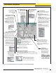
Figure 5-11. Control Mode selections
(PSF Configuration screen)
Figure 5-10. Selected Controller and Serial
Communication
selections (PSF Configuration
screen)
Control Module Configuration
Banner Engineering Corp. •Minneapolis,U.S.A.
www.bannerengineering.com•Tel:763.544.3164