
Owner manual


P/N64118rev.B
Control Module Configuration
22
Banner Engineering Corp. •Minneapolis,U.S.A.
www.bannerengineering.com•Tel:763.544.3164
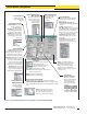
Figure 5-9. Use the PSF Configuration screen to program each control module individually
Serial Transmission
Specifiesthetypeofdatatransmitted
fromthecontrolmoduletoitshost
aftereachscan.
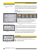
Measurement Mode Result:Data
transmittedwillreflecttheAnalysisMode
selections.
All Mode:Transmitsalldata.
Max. Meas. Mode: Sendsonlythelargest
measurementineachmeasuringevent,to
decreasetransmissionsizeandspeed
response.Choosetosendwhenthearray
isclearorsendatthehost’srequest.
Transmission Type: ASCIIorBinary,
definestheformatinwhichthedata
willbesent.
Serial Options:SuppressClearData
orSuppressHeadertodecrease
transmissionsizeandspeedresponse.
Analysis (Measurement)
Mode Selection
Choosethemeasurement
optionthatbesttellsyou
thesizeand/orposition
ofobjectsasthey
relatetothearray.
Control Mode Selection
Continuous Mode:Thecontrol
moduleconstantlypolls
thearrayforstatus.
Host Mode:Thecontrolmodule
pollsthearrayforstatuswhen
promptedbyahostcontroller.
Gate Mode: Thecontrolmodule
pollsthearrayforstatuswhen
promptedbyaninputfroma
Gatesensor.
Scanning Method
Straight scanpollseachbeam
sequentiallytodeterminethetarget
object’soverallsize.Thisisthemost
accurateandprecisemeasurement,
butalsothemosttime-consuming.
Single Edge scanrequiresthetarget
objecttoblockbeam1(closestto
thesensors’cabledends),then
conductsatime-savingbinary
searchto“hunt”forthetarget’s
overallheight(onevariableedge).
Double Edge scanconductsa
time-savingsearchoftheentire
arrayto“hunt”forthetarget’s
overallwidth(twovariableedges).
Set Point and
Hysteresis Selection
Assignsthesetpointto
determinewherewithinthe
arraytheoutput(s)will
respondandhysteresis
valuestosmoothoutput
response.
Trigger/Trigger Channel Number
Maybeusedtotrigger(orgate)thescansequenceofanother
A-GAGE High-Resolution MINI-ARRAYcontroller;instraightscanning
mode,itdefineswhenduringeachscandiscreteOutput#2willchange
state.
Scan #: (1-9)Analogoutputsare
updatedwithanaveragevalueofthe
datareceivedduringtheselected
numberofscans;discreteoutputs
respondonlyifthereceiveddatais
identicalforalloftheselectednumberof
consecutivescans.
Analog and Discrete
Output Assignment
Assignsananalysis
(measurement)mode
toeachoutput.
Alarm:Causesthecontrolmoduleto
turnondiscreteOutput#2whenever
theSystemdetectsasensingerroror
iftheopticalsignalbecomesmarginal.
Selected Controller
Identifiesthespecific
controlmodulebeing
configured.
Serial Communication
Changestheidentification
andbaudrateofthe
controllerbeing
configured.
Zero Value
ZeroValueisusedtospecifythe
analogoutputwhenthe
measurementmodevalueiszero.
Theusercanspecifyavalue
ofLAST,NULL,orSPAN.
LAST: Outputholdsthelastnon-zerovaluebeforethe
lightscreenbecameclear.
NULL: Providestheminimumvalue.
SPAN: Providesthemaximumvalue.